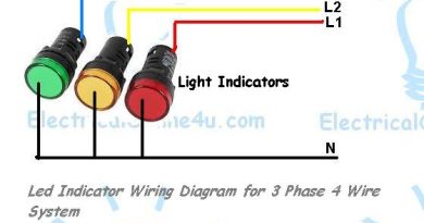
Current Transformer Installation For 3 Phase- CT Coil Wiring Diagram
As You know that I already published posts about the CT Coil current transformer installation wiring and installation with Ammeter. But in this post, you will learn about how to install the current transformers in three phase. As you know that always we need a ct coil and ampere meter in the main panel board for measuring amperes (Load). One thing in this post I will show you the image of three current transformer installations in the main power panel board.
Recently I capture an image of ct installation on a panel board. In the panel board, we use three colours for the three-phase power supply Red, Yellow and Blue and black neutral and green for the Earth connection. However, in this post, you will learn the installation and wiring connection of three CT – Current transformers and the wiring connection of ammeters.
Three Current Transformer installations – with Ammeters for Three Phase Supply
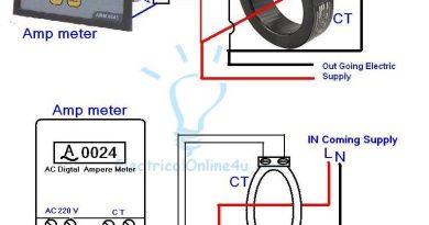
The connection of CT is too easy and the best place to the installation of CT in the electric power panel board is to connect it with incoming supply wires and connection. Mostly we use Copper Strips for the main sharing connection in the power board because we can easily get power connections from copper strips and better for high loads. In the below image, I show CT Coils installation with copper strips.

So In the above image, I have shown how to install the CT coils for three-phase but this is just an image, not the full and complete ct coil wiring guide. As you know that I always try to teach completely and write a complete and simple post which easy to understand.
So how to connect it with ammeters, so for amp meter wiring learning I published a post and if you don’t read our last post then kindly read it before the below post. and then come to this page.
How to wire an ammeter with a CT coil?
How to wire a digital amp meter with a Current transformer?
How to wire a Digital Ammeter, volt and HZ meter with CT and supply?
Mostly we install an ammeter selector switch for three CT coils, from which can check all phases load with one ammeter I will also publish a post about this soon but here I the below CT diagram, I don’t use a selector switch because this is a basic post and after that, we will write with details in other time.

In the above diagram, I have shown three ammeter current transformers, in the above CT wiring diagram, I common a wire of all CT s, which means that I connect CT one connection with one another. I can also do it without connection with one another but the main reason behind this is that in real life we do our wiring like the above diagram in our main power panel boards. I showed three phase supply with red, yellow and blue colour lines. So in this post, you learn about the installation of a current transformer and IN SH ALLAH Soon I will write about the current transformer installation CT coils with Ammeter and voltage selector switch.

why don't we connect a single ct coil directly to a single phase .. i mean why there is need for common all the am meter terminals and ct terminals ?
Dear you can also do this connection with your method but in electrical panel board if you do this wire single single ct to meter then this will be waste of wire and time.
how to install 3 ct and 1 amp meter and 1 amp selector switch
Can you please tell me how to connect CTs to meter (3 phase wiring)
Dear i make a diagram about this you can find it by using our blog search" search selector switch" and you will be find it.
i have one machine which has input is 220 volt 3 phase (6 amp, 1.5 kw). how i connect this machine?
Great job for publishing such a beneficial web site. Your web log isn’t only useful but it is additionally really creative too. There tend to be not many people who can certainly write not so simple posts that artistically. Continue the nice writing check PressureWasherGuides.com
Your blogs are easily accessible and quite enlightening so keep doing the amazing work guys. jubilee health insurance – Personal accident protection
I would like to say that this blog really convinced me to do it! Thanks, very good post. Power Efficiency Guide Review
Can you connect more than 1 meter to a single CT, by having a series circuit?
Brad
Being an electrician is not easy as you are always at high risk so why not have a health insurance in Pakistan or workmen’s compensation insurance and feel secure.
Taking care of health is one of the most difficult task in our life however health insurance in Pakistan makes it easier and along with it we should choose one of the best insurance company in Lahore
Keep up the good work , I read few posts on this web site and I conceive that your blog is very interesting. home health care new york
While every one of the gatherings will have their own view on the current 'greenness' anytime of time and how the green supply chain project is advancing, just an extensive execution assessment approach can accomplish an agreement perspective on the circumstance winning anytime of time. mélybölcsős szállítás Europa-Road Kft.
I love electric engineering but never understand coil loops i do at home different experiments.. Always fails and then learn Guided and unguided media of networking
This is such a great resource that you are providing and you give it away for free. I love seeing blog that understand the value of providing a quality resource for free. tenant information update form
Smoking is a killer habit, pretty literally, and one which for lots is tremendously difficult to shake. In latest years, vaping has arisen as a cappotential opportunity to smoking, one that during a few approaches and for a few humans can be a more fit option.IQOS delivery
In the United States, Medicare is a social insurance that is offered to all citizens over the age of sixty five. medicare agent near me
Hi thank you for the post. But my question is,why need common? why don't we connect a single ct coil directly to a single phase?
I have one question to you brother, How Much Horsepower Does a Horse Have?