Permanent Split Capacitor Motor Wiring Diagram
Nowadays we have mainly used the permanent split capacitor motor. The post is about the single-phase permanent split capacitor motor wiring diagram. In the diagram, I have shown the complete wiring connection with the power source (220 VAC), Motor internal winding connection, and motor running capacitor.
Also Read:
Capacitor start capacitor Run motor wiring diagram
Permanent Split Capacitor Motor Wiring Diagram
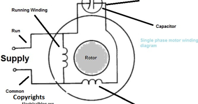
In Single phase motors, we have two types of windings, Main and Auxiliary windings. In the below permanent split, capacitor single-phase motor diagram. I have shown the wiring connection of the main and auxiliary windings. The link where we connect both windings is called the Common Wire. The other side of the Main Winding is called “Run” and the auxiliary winding other side is Called the “Start” wire. The supply is connected to the Common and Run wire. The Running Capacitor is connected between the “RUN” and “START” wire. As I have shown in the below diagram.

The above diagram it too simple to understand, however, if you have any questions or suggestions, you can use the below commenting system.