Single Phase Motor Capacitor Start Capacitor Run Wiring Diagram
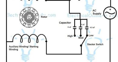
Today I am writing about the single phase motor capacitor start capacitor run diagram. In single-phase motor windings, we have two types of windings: Main winding (Running winding) and 2nd is Auxiliary winding (stating winding). With single-phase motors, we use two types of capacitors Staring and Running capacitors. In some single-phase motors we use starting capacitor with a centrifugal switch; in some, we use a running capacitor direct with auxiliary winding and power source. And in some single-phase motors, we use both Starting and Running capacitors. In this post, I share a One-phase motor capacitor start and capacitor Run wiring connection diagram.

In the above single-phase motor capacitor and capacitor run diagram, I have shown the motor auxiliary and main winding. I have shown the starting capacitor with the centrifugal switch and the Running capacitor direct to the motor auxiliary winding. The above diagram is too simple and easy to understand. And I think there is no need to explain it more. However, if you have any questions according to the diagram or want any suggestions then use the below comments section.
Also Read:
Why Starting Resistance is High
4 Pole Single-Phase Motor Winding diagram