Contactor Wiring Diagram For 3 Phase Motor
This post is about the magnetic contactor wiring diagram for 3 phase motor. In the post, you will learn step by step how to wire the magnetic contactor, thermal overload relay, MCCB (moulded case circuit breakers), Normally Open push button switch, normally close push button switch, and Red and Greenlight indicators. This will be the complete guide of a direct online starter for 3 phase motor. And in the next post, I will share a diagram about the contactor wiring with a timer.
Magnetic contactor wiring diagram for 3-phase motor
Before we start about the complete wiring of direct online starter or contactor wiring with MCCB and thermal overload relay. First, we discuss all things step by step.
Magnetic Contactor
A magnetic contactor is a type of electromagnetic relay or switch. Which we use for controlling electrical devices such as compressors, 3-phase motors, single-phase motors, etc. In short, it’s a type of starter for electrical machines. A contactor has 3 types of contacts. Main contacts are used for controlling the load or machine. Auxiliary contacts which used for different types of interlocking systems. And coil contacts where we provide the electric supply to operate the magnetic contactor.
Also read:
MCCB Circuit Braker (Molded case circuit breaker)
As you know there are different types of circuit breakers, just like MCB, MCCB is also a well-known breaker and is mostly used in the electrical distribution board. And a 3-phase panel board is incomplete without an MCCB circuit breaker. The MCCB circuit breaker can be 2 poles, 3 poles, and 4 poles. For the single phase we used the 2 poles, for 3 phase we used the 3 poles,s, and for the three-phase 4 wire system, we used the 4 pole MCCB circuit breaker. In today’s magnetic contactor wiring diagram for 3 phase motor, we used the 3-pole MCCB circuit breaker.
Thermal overload relay
A thermal overload relay is a protection device that is used to protect the motor from overloading and overcurrent flow. When the overcurrent flow in the circuit, the thermal overload relay trip the motor.
In the thermal overload relay, we have current adjustments, “H” and “A”. where “H” is for hand and “A” is for automatic resetting. NC and NO points, where NC for a starter or motor tripping and NO for a tipping signal.
Normally Open Push Button And Normally Close Push Button Switch
A normally open push button switch is a normally open circuit which is used for switching On the circuit. And normally close push button is an internally closed circuit in a normal state. Which is used for switching off the circuit.
Lights Indicators
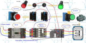
In the contactor wiring diagram, 2 light indicators are shown, green and red. The red will glow up when the motor trip and the green light indicator will glow up when the motor start.
Now let’s talk about the magnetic contactor wiring diagram for 3 phase motor. In the below diagram, I have shown an MCCB circuit breaker, contactor, thermal overload relay, NC/NO Switch, and light indicator.
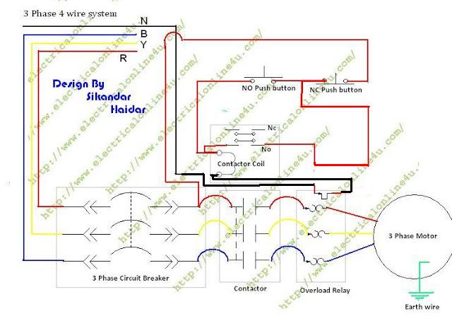
First, we will start with the main wiring power wiring. The three-phase supply shown in the diagram, L1, L2, L3 which is connected to the MCCB circuit breaker, and after that the supply goes to the magnetic contactor and from the contactor, the supply goes to the thermal overload relay, and from the thermal overload relay, the supply goes to 3 phase motor. In the below diagram, the motor connection is shown in the star connection.
Now come to the control wiring. The NC switch is used for switching off the starter, and the normally open push button used for switching off the starter. The neutral wire is connected to the thermal overload relay NC points and from here the neutral supply goes to the contactor coil. A line wire is connected to the overload relay NO points and from other points, the supply goes to the red light indicator. Which will glow off when the relay trip.
In the above diagram, “H” means holding wire, and “T” means tach wire.
Also read:
I hope the direct online starter wiring diagram with thermal overload and light indicator helps you to understand the contactor wiring, however, if you have any questions according to this post you can ask your questions in the below comments section.


This comment has been removed by the author.
the point 3 phase power supply is incoming power or to the load