DOL Starter Wiring Diagram 3 Phase Motor
We use three-phase motors mostly in many places, in this post you will learn the dol starter wiring diagram 3 phase with complete circuit breaker, contactor, and overload relay diagram step by step. We required some electrical things for three-phase motor wiring which are below.
Requirements
3-phase induction motor
3-core electric cable
Three-phase 4 wire system supply (three-phase and one neutral)
A circuit breaker
A contactor or starter
An overload relay
and flexible wiring cable for controlling the wiring
Normal close push button
Normal open push button
Before we start talking about the wiring and wiring diagram, first we disuse the above substance. We required 3 core cable, a three-core cable is a cable that has an internal three-electric cable mostly in red, yellow, and blue colours. The three-phase 4-wire system supply means that we need 3 phase electric supply and one neutral wire. Note that we use the neutral wire for contactor coil wiring which we called the control wiring.
We also required the circuit breaker which is a 3 pole circuit breaker or circuit breaker which can cut off the 3 electrical connections at the same time.
A normal close push button (NC) means that we need a push-button which normally has a close electric circuit and when we push it then the button switch off the connection or changes to the open electric circuit.
The normal open push button means that we need a push-button which have an open electric circuit in a normal state and when we push it then it’s changed to the close electric circuit.
Dol Starter wiring diagram for three-phase motor
To wire a 3-phase motor the first thing to wire is a circuit breaker which is a disconnect and connecting point then we will get the supply from the circuit breaker and connect the supply to the contactor or starter and then to the overload relay. We connect the circuit breaker, contactor, and overload relay in series between the electrical supply and motor as shown in the below diagram.
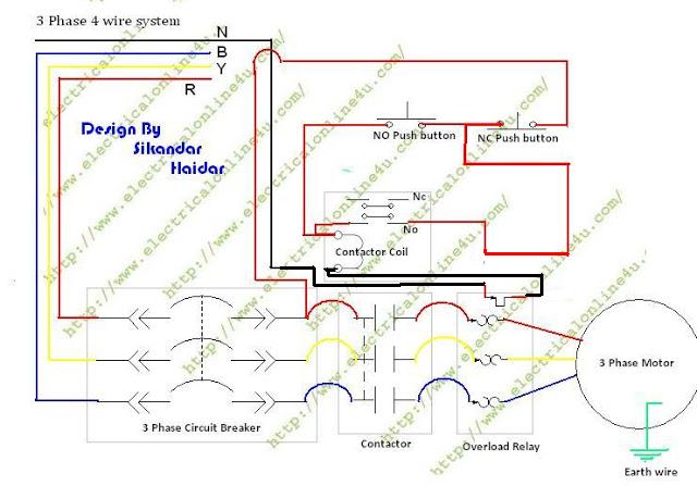
Contactor and Overload Relay Wiring
In a contractor, we have a magnetic coil that is used for switching. We have also NC and No point in a contactor which we can use for many connections. In the overload relay, we have input and output points. Normally overload points have a close electric circuit between point but whenever the ampere or load is getting high the overload relay switch off or make an open electric circuit between these two points or connection. So we wire the overload relay in series between the contactor coil current.
So for contactor wiring first of all connect the neutral wire to the contactor coil’s first terminal and then connect a wire from the one output terminal of the circuit breaker which is the opposite or phase current for the contactor coil. In this process, the control wiring which is contactor wiring is also controlled by a breaker, and when we switch off the breaker, the contactor will stop working auto.
The control wiring wire which connects from the breaker output terminal will go to the NC push button and then from NC push to the overload relay and NO push button as shown in the above diagram. Then we connect a wire between the 2nd terminal of the overload relay and this wire goes to the NO point of the contactor and then from NO point wire is goes to the 2nd terminal of the contactor coil.
Then at last, we connect a wire between the NO push button switch and the contactor 2nd terminal of the coil where we connect the phase wire of the contactor as shown in the above diagram. And this wire connection is called tech current.
Final word
Note that in all wiring use the best quality breaker, push-button switches, contactor, and overload relay. If your overload relay is not good then it will not trip and if the overload relay does not trip or does not switch the point then it will be a case of your motor burn. Note that do all wiring controllable from the circuit breaker as I showed in the above diagram.
Note that always connect the earth wire to the motor, and adjust the overload relay ampere by using the adjustment switch.
Message
I spend more than 2 hours on this article writing and designing DOL Starter Wiring Diagram 3 Phase Motor diagram, so if you learn some important things then it’s your responsibility to share. Now if you have any questions regarding the 3 phase motor wiring diagram then you can ask me in the below comment section.
All your posts are knowledgeable , keep it up bro
thanks dear for liking our posts…………
Thanks a lot for shearing your valuable knowledge.
Thanks for liking our post…… I Always try my best post best articles about EEE Technology.
IN SHA ALLAH soon i will publish my new websites which help you more in electrical technology learning…….
Hi bro,
will you please brief expalanation about wiring of overload relay using contactor
Dear soon i will write about this overload relay wiring using contactor.
salaams, you make it so simple to understand, thank you
salaams, you make it so simple to understand, thank you
Thanks dear
hello brother
Your article is very helpful to me.i really appreciate your work brother.
May GOD bless you.
I have a scenario in which i have a 3-phase motor of 7.37hp, 7.9A & i want to connect an overload relay & relay contractor to this motor.
Brother can you please tell me which contactor and overload is suitable for my scenario?
I will be very thankful to you for this favour.
Dear your motor is 7.37 HP so if the voltage is 440v then your motor will get 11 amps. But you said that your motor getting 7.9 amps on running mode. So regarding your data 7.9×2= 15.8 contactor for this motor but some time voltage can be high or low then we plus the 20% extra
So 15.8×20/100 = 3.16
So 15.8 + 3.16 = 18.96
So as 18.96 contactor not avilable in market then you can use 20 or 22 one th contactor for your motor.
So the next thing what is amps of relay for your motor. Use an overload relay which can word up to 12 amps. For example if your overload relay is work form 5 to 12 amps. Then set your relay amps on 9 amps.
If you need more help then you can ask me again.
asslam alaikum bro.. jazakallah for your more information about electrical.. ji my question was how to select the MCB for control panel?
Wonderful article. Really informative. Keep up the good work. Kindly assist me on how you set the overload relay. Thank you.
kindly do.i have learning alot from you Haidar.Many blessings
I truly appreciate this post. I’ve been looking everywhere for this! Thank goodness I found it on Google. You’ve made my day! Thanks again.. https://royalcbd.com/product/cbd-gummies-25mg/