Digital 3 Phase Voltmeter Connection Diagram For 440 Volts Testing
In three phase power system, we wire and install the voltmeter to measure the AC voltage, in this post, you will learn about the 3 phase voltmeter connection diagram for a digital voltmeter. I have already published posts about the three-phase voltmeter wiring/installation. Also the voltmeter selector switch wiring diagram/installation for 3 phase and also for the three-phase 4-wire system. In his post, I am going to write about the three-phase digital voltmeter wiring for single phase and 3 phase, but I only share the diagram about the 3 phase digital panel voltmeter, which I use for the line-to-line voltage measurement.
3-Phase Voltmeter Connection Diagram For Line To Line Voltage Testing (440V)
In a 3-phase analog voltage meter, we have 2 terminals or contacts to provide the supply. We can connect our single-phase (neutral and Phase) to these connections or connection points to measure the voltage between neutral and phase. But as you know the meter is designed for a three-phase system (0 to 500 volts) so always use it for measurement of voltage from line to line (phase to phase).
So we connect two lines (i.e. L1 and L2) to an analog voltage meter to measure the voltage between Line 1 to Line 2. But in digital we have some different connections and we also required the neutral or we can say if we are going to install a digital voltmeter to measure the voltage between line to line then we also required the neutral to operate the digital voltmeter.
In a digital voltmeter, we have two types of input contacts, one to operate the digital V meter or to operate the display of the meter. The 2nd input for voltage to measure. Here I had shown a diagram in which I wire the voltmeter for measuring the voltage between L1 and L2.
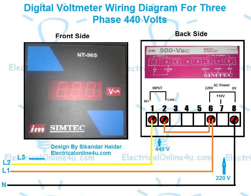
In the above digital 3-phase voltmeter connection diagram. I showed the neutral and phase supply goes to 6 and 8 terminals for the voltage meter which is for operating the display. As the L1 is connected to the 6-number terminal and this is also line then a wire connection will go from this point to the 2-number terminal.
The 1 and 2 number points are for input AC supply to measure. So we connect the L1 to the 2 number and the L2 wire to 1 terminal.
The above connection for the digital voltage meter is for line-to-line voltage testing. However, if you want to wire it for single phase (Neutral to Phase) voltage testing then provide also the single phase 220 supply to the 1 and 2 terminals.
Note the connection diagram can be different for the different models of voltmeters. It depends on the company that manufactures the voltmeters. So this is just an example of a wiring connection. It’s an incoming supply for display and the number of terminals can be different in different models of the voltmeter. So the better option is to read the guide or diagram of the voltmeter, which is provided on the side or backside of the voltmeter. Here is the above voltmeter example…..

In the above image, the voltmeter connection method is shown. In which High and Low for input AC supply voltage testing. Note this meter can test voltage from 0 to 500v. In the above diagram AC power terminals are 6, 7, and 8 but in meter only 6 and 8 number of contacts are available for 220 volts. However, if the 110 V option is available and your supply is 110v connect your supply to 0v and 110v contacts.
(Note every voltmeter has its own diagram and its own connection. So this is not important that the connection name and number are the same. Or the connection method the same. So always read the digital meter contacts diagram and then wire it)