14 Pin Relay Base Wiring Diagram
In Controlling relays “14 pin relay” is numbering in those electromagnetic relays which we use in many circuits. In this post, I am sharing the 14 pin relay base wiring diagram. With 14 pin relay, we use the base or relay socket in which the relay is inserted. In the 14-pin relay, we have 14 pin or connection terminals in which the 4 terminals are common terminals, 4 terminals are N.C (normally closed) with common terminals, 4 terminals are N.O (normally open) with common terminals, and 2 terminals for relay operating coils. This relay we use for different types of control circuits.
14 Pin Relay Base Wiring Diagram – Finder 14-Pin Relay Socket Diagram
In this post, you will learn about the 14 pin relay base wiring diagram. On the relay, we have the wiring diagram in which all terminals are shown with their working principles.
As I said above that in the relay we have 14 pins which are numbered from 1 to 14.
In which :
13 and 14 are for the relay coil
9 is NC with 1 and NO with 5
10 is NC with 2 and NO with 6
11 is NC with 3 and NO with 7
12 is NC with 4 and NO with 8
Below I showed the 14 pin relay diagram with 14 pin relay base. This is also the 14-pin relay base wiring diagram.
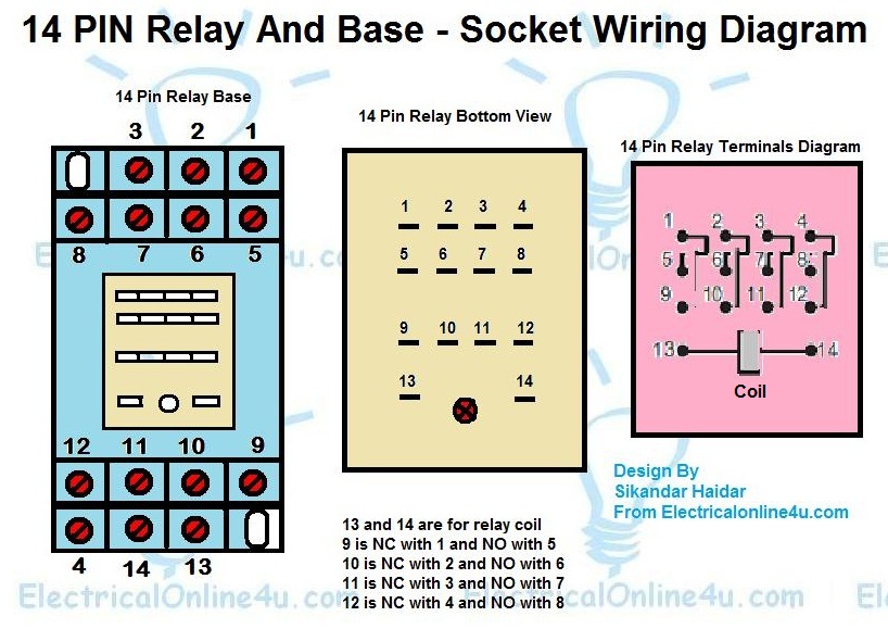
In the above 14-pin relay base wiring diagram or socket wiring diagram. I have shown the 14 pin relay and its terminals with numbers. Then I showed the bottom view of 14 pin relay and then 14 pin relay wiring diagram. The relay base will be wired according to the relay. For example, in the relay, we have 14 and 13 number terminals for the relay operating coil. So in the base, the 13 and 14 number terminals are for the relay coil. Note that this relay can be different according to the rated voltage and power source type. Mostly this relay is available in the market in DCV 12, DCV 24, ACV 220 Volts, and much more. And mostly designed for 5 Ampere load control.
Also, Read
Digital Multi Voltmeter Ammeter Hz Wiring With Diagram
This post is only about the 14 pin relay basic wiring diagram. In the next post, we will use different circuits for different types of control. I hope this 14 pin relay base wiring diagram and relay diagram help you to use this relay in circuits.