Extension Board Wiring Diagram
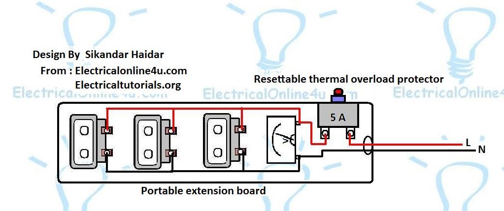
Extension Board wiring is the topic of the day. In today’s post, you will learn about the portable extension board wiring with a simple diagram. In the extension board, wiring diagram the three 2-pin outlets are shown, a one-volt meter is shown, and one resettable thermal overload protector is shown. The complete wiring diagram is shown below.
Extension Board Wiring Diagram
In the above extension board diagram, the neutral and line wire supply comes to the board. The neutral wire is connected to the voltmeter and each outlet. The line wire is connected to the resettable thermal overload protector. From the output side of the overload protector, the line wire goes to the voltmeter and all three outlets.


Thank you for this topic I am interested in, thank you for providing extremely useful information.
By the way, I have a few products you can consider adding https://besttoolsadvisor.com/
Portable Air Conditioner
Quiet Portable Air Conditioner
portable ac
best portable air conditioner
windowless air conditioner
14000 btu portable air conditioner
portable air conditioner and heater
portable air conditioner with heater
Ok