Manual changeover switch wiring diagram for portable generator
Today I am writing about the manual changeover switch wiring diagram, as you know that we use the generator as an emergency power source in our house wiring, we can do the generator changeover system in two methods, in which one is manual and 2nd one automatic system. This post is about the manual changeover switch wiring diagram for a portable generator, and IN SHAA ALLAH we also write and make a diagram about the automatic changeover switch wiring which we have known better with the name of the ATS system. (Automatic transfer switch)
Electrical Manual Changeover Switch Wiring Diagram For Portable Generator
Manual changeover switches are mostly used in 2 types, one has the moveable knob and 2nd one is the handle changeover switch. In this post, I will show the complete method of manual or handle change-over switch, the knob-type manual changeover switch wiring same as the handle change-over switch and it’s just like a voltmeter sector switch.
In this post I am explaining type one, Below I have shown the single-phase manual changeover switch with image and connection & manual changeover switch wiring diagram with the complete connection of the main supply and generator supply and outgoing supply to the load.

In the above manual changeover switch wiring diagram, I have shown the incoming supply from the energy meter, incoming supply from the portable generator, and outgoing supply to load or house load.
In the diagram, I showed handle type manual changeover switch. in which I done all the connections. One thing more always do earth connection to the changeover body, if you have the earth wire. This connection can also work without the earth or ground connection, But in Electrical Works the most important thing is safety so always do the ground connection.
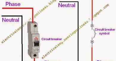
In the above diagram the black colour denotes the neutral wire, the red colour denotes the phase wire (Line / Hotwire) and the Green colour denote the earth/ground wire.
After this diagram, I hope now you will be able to connect a portable generator to the house load. here I have an image of a handle-type manual changeover switch which capture with my mobile camera.

In the above manual changeover switch/transfer switch image, the connection is not done, and not a proper method of installation and wiring, however, I capture this image just for you to see the manual changeover switch/transfer switch internally.
I hope after the above image and manual changeover switch wiring diagram, now you will be able to connect a portable generator to your house wiring. IN SHAA ALLAH soon I will make a diagram about the connection of a portable generator to a distribution board or how to connect your portable generator to your distribution board.
solar l lay kn se battrey best hai
Impressive work on the essayist's part. check out this
Impressive work you provided some people do not know about best portable generator value
impressive and satisfying. helps a lot of electricians.
Wao so helpfull thanks
Do you have an APP or a PDF file for this, so i could download. I really love the manual guide.
Appreciate it for this post, I am a big fan of this website would like to continue updated. used generators for sale
Where exactly do I find a transfer switch like the one you have pictured above?
I admire what you have done here. I like the part where you say you are doing this to give back but I would assume by all the comments that this is working for you as well. generator sri lanka
It's really good lessons..
Hello wanna know how to wire a star Delta using solar energy