Automatic Water Level Controller Wiring Diagram
This post is about the automatic water level controller wiring diagram. As you know that there are different types of water level controllers available in the market or online markets. But all liquid-level controller wiring connections and installation are mostly the same. In this post, I am sharing with you the automatic water lever controller diagram with a complete installation method. You can buy this water level controller from amazon.com. However, this diagram helps you to understand the wiring and installation of a water level controller.
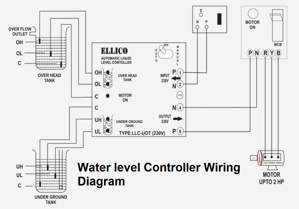
Automatic Water or Liquid Level Controller Wiring Diagram.
The below diagram is about the water level controller. In the diagram, a water level controller is shown with a motor starter, a water level sensor with an overhead tank, and an underground tank. You
can run the motor manually and automatically using the switch. You can use this water level controller for single phase motors, 3 phase motors, and also for DC water pump motors. However, you need some more starter for controlling the motor. In the next post, I will share a diagram that helps you to understand the installation of a water level controller. Note that if you want to use the controller for one tank then common three wires with one another. For example, if you want to use it for only the overhead tank. Then common C, UH, and UL with one another.
I hope this ellico automatic water level controller wiring diagram helps you. This controller is made by ELLICO and you can buy it from Amazon.


100% successful
Can you please share complete diagram with sensor names etc
I did this wiring diagram this week. The company requested an COC Certificate on this job so called COC Pretoria to give me an electrical certificate for my compliance certificate. Is this normal in other countries for a compliance certificate on your electrical work or this just something that happens in Pretoria South africa|?
Nice work
I utilized it for a month and saw a discernible distinction in myself. Presently I don't short of going out with my companions and so forth. asbestos inspector
Thanks for a very interesting blog. What else may I get that kind of info written in such a perfect approach? I’ve a undertaking that I am simply now operating on, and I have been at the look out for such info. view more
I think this is an informative post and it is very useful and knowledgeable. therefore, I would like to thank you for the efforts you have made in writing this article. well mate 80 gallon pressure tank
This blog is so nice to me. I will keep on coming here again and again. Visit my link as well.. superwinchatv winch
I will be interested in more similar topics. i see you got really very useful topics , i will be always checking your blog thanks anti deriv calc
you have got a great weblog here! do you wish to make some invite posts on my small weblog? https://royalcbd.com/product/cbd-oil-500mg/
Nice collection.. I liked Ubuntu Tilting Font, using in my current project.. Brain Training for Dogs Review: Does Adrienne’s System Work?
This is my first time i visit here and I found so many interesting stuff in your blog especially it's discussion, thank you. express keto customer reviews
Thanks for sharing us. does septifix work