Autonics Fx4 Counter Wiring with Direct Online Starter | Proximity Sensor Diagram
This post is about the autonics fx4 counter wiring with a direct online starter and proximity sensor with a complete diagram. In the post I showed a diagram of the complete wiring of a direct online starter with MCCB circuit breaker, magnetic contactor, thermal overload relay or 3 phase motor protection relay, Normally open push button switch, normally close push button switch, fx4 counter and proximity sensor with complete wiring connection.
The wiring is divided into two parts. main wiring and controlling wiring. First I will talk about the main wiring which is about wiring for the 3-phase induction motor. And the 2nd wiring is controlling of direct online starter with Autonics fx4 counter with the proximity sensor.
Autonics Fx4 Counter, Proximity Sensor Wiring With Direct Online Starter Diagram
First, see the autonics fx4 counter connection with a direct online starter diagram. Then I will explain step by step…
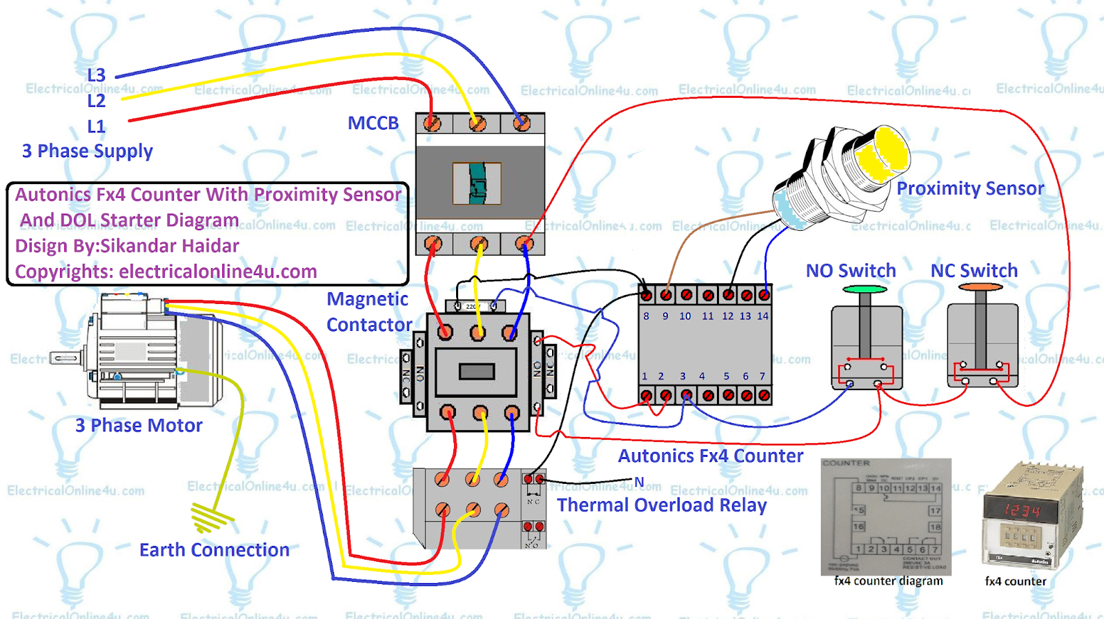
In the above counter with the dol starter diagram. The 3-phase supply L1, L2, and L3 (red, yellow, blue) is connected to the MCCB (moulded case circuit breaker).
After the MCCB Circuit breaker, the main supply is connected to the magnetic contactor main terminals. And after the contactor, the 3-phase supply goes to the thermal overload relay.
After the thermal overload relay, the 3-phase supply goes to the 3-phase induction motor. The earth connection is also connected to the 3-phase motor.
Control Wiring Of Autonics Fx4 Counter For DOL Starter with Proximity Sensor
The magnetic contactor and fx4 counter will work on 220 VAC. It means that we also need a neutral wire. So first of all connect the neutral wire to the NC terminal of the thermal overload relay. if you connect it to the 95 terminal then get the supply from the 96 terminal.
After that provide the neutral wire to the contactor A1 coil terminal and counter 9 terminal. As I showed the neutral wire connection with black colour in the above diagram.
After getting the line supply from one of the above lines. I get the Line wire from the L3 which you can see in the above diagram. The line wire is shown in red colour. The line wire is connected to the normally closed push button switch.
After that, the wire goes to the normally open push button switch. From there a red colour wire goes to the Normally open auxiliary contacts for the magnetic contactor. This is called hold current wire.
After that, the holding wire will go from the other side of the auxiliary contact and connect to the counter 1 and 2 terminals.
From the normally open push button switch, a blue colour wire will connect to the counter 3 terminal and contactor A2 coil terminal. This is called touch or starting current wire.
That is all. Soon I will upload a video about the autonics fx4 counter connection with direct online starter and proximity sensor working video and a diagram explanation video.
Also, read…

Good
Very nice
awesome
Aw, i thought this was an incredibly good post. In thought I would like to invest writing such as this moreover – taking time and actual effort to have a top notch article… but exactly what can I say… I procrastinate alot and by no means apparently get something done. https://royalcbd.com/product/cbd-oil-2500mg/
This is great innovation
This is the system i used to build an Auto timer but on a single phase.
Great post, you have pointed out some excellent points, I as well believe this is a very superb website. cambodia real estate