3 Phase Wiring Installation In Multi Story Building
In house wiring, we install two types of wiring of which one 3 phase wiring installation for the house and the other one single-phase installation. In this post, you will learn how to install three-phase electrical wiring using a simple diagram in which I have shown how to install a three-phase 4-wire system in a multi-story building. One thing more that I have shown 3 distribution boards in which every story has its own electrical main distribution board.
3 Phase Wiring Installation In Multi-Story Building / House
The three-phase 4 wire system installation at home is very simple but to understand you must study each part of this class and the devices that I use in the below diagram. I start this from step one.
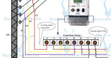
Utility Pole 3 Phase 4 Wire System
The diagram starts from the utility pole and I get the service line supply from the utility pole to 3 phase kWh energy meter. This utility pole connects to a step-down transformer (supply from the substation). This means that the pole supply comes from the substation or step-down transformer.
3 Phase kWh Energy meter
I also have shown the wiring diagram for 3 phase 4 wire system kWh (kilowatt-hours) meter, I also published a post about the wiring and installation of three phase four wire system kWh energy meter. So kindly read the below article if you did not understand the method of 3 phase kWh energy meter connection.
Also, read
How to wire and install the 3-phase kWh energy meter?
How to wire Single phase kWh meter?
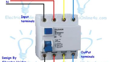
4 Pole MCCB Breaker
After the connection of the energy meter, I connect the 3 Phase 4 wire power supply to the MCCB (module case circuit breaker). However, if you can do this connection then read the below post.
Also, read
How to wire 3 Pole or 4 Pole MCCB Breakers?
Now come to the connection for the distribution board for one story. The method of installation 3 phase wiring is simple, you divide your load into three parts and each part has there own Line (phase). My means that divide your load into 3 parts and provide one phase to each part.
Now here I have a multi-story building in which each story has there own single-phase, distribution board.
So we will provide one phase or line to each story. And our neutral will be common but this will be common in circuit breaker output points and each story has its own neutral wire. So provide my Line 1 or phase 1 to the first distribution board as you can see in the diagram. So come to the Distribution board.
Distribution Board Wiring Connection
In the DB board, I use the following electrical devices.
Double Pole MCB Circuit Breaker 63 Amps
I get phase and neutral wire from the main circuit breaker( 4 pole MCCB) and connect to double pole MCB (miniature circuit breaker). Note that double pole MCB will be considered the main circuit breaker for the single phase distribution board below the diagram.
Also, read below
How to wire double pole MCB breaker?
How to wire and install single, double, three, and four-pole MCB (miniature circuit breakers)?
RCD Breaker.
I also install and wire double pole RCD (residual current device) in each distribution board. If you did not understand the wiring and installation of RCD then read the following post.
Distribution Electrical Board Wiring for Single phase
How to wire and Install the double pole RCD breaker?
How to wire a 4 pole RCD circuit breaker?
Earthing or ground connection
I also did the earthing connection in 3 phase wiring installation diagram in multi-story house. I have shown this connection by using an earth symbol and a green wire. In the below diagram the earth, symbol consider as the earth electrode.
Also, read
How the earthing system works for protection?
AC Voltmeter Wiring connection for single phase
I also do the voltmeter wiring connection is each distribution board and you can see it in the diagram. However, here is some post which helps you more than this. (Note that the VM denotes the ACV voltmeter below diagram.
Also, read
How to wire a voltmeter for single-phase?
How to wire voltmeters for Three-phase?
How to wire voltmeter selector switch for 3 phases with a voltmeter?
How to install the voltmeter selector switch for the 3-phase 4 wire system?
How to wire light indicators for the 3-phase 4 wire system?
Ampere meter / Ammeter connection with CT (current transformer)
I also have shown the ammeter connection with the current transformer in 3 phase installation diagram for a multi-story house. The connection of CT is simple with ammeter but this will be better for you if you read the following articles.
How to wire an ammeter for AC and DC?
How to wire the ammeter with the current transformer?
How to do digital ampere meter connection with CT Coil?
Complete Explanation of Three – 3 phase wiring installation in a multi story building
The installation of three phase 4 wire system in multi-story building is simple if you want to use single phase supply for each story. Note that by doing this type of connection you must wire 4 distribution boards. where one for the main MCCB circuit breaker and the other for each story. And you can also do these connections in a single main DB but you must use a big size distribution board box where you can easily install all circuit breakers. But if use their owns distribution board in every story then this will be a better option.
So let’s do it step by step.
In the 3-phase wiring diagram, I have shown a utility pole from where I get a service line connection for 3 phase kWh meter (energy meter). Now I connect the supply wire Red, Yellow, Blue, and Black to the energy meter input connection terminals and get the supply from the energy meter outgoing connection to load.
One thing more is that we use a colour code of red, yellow, and blue when doing the three-phase wiring, but when it comes to the 3 phase four-wire system, we use black for neutral. And when we are gonna do connection of single phase ( current between phase and neutral) then we use red for phase (hot wire) and black for neutral.
After the connections of three phase kWh meter, we provide the 3 phase 4 wire supply to 4 pole MCCB circuit breaker which is on the- 100 amp. Now the next step is outgoing supply from the 4-pole MC CB circuit breaker. The N neutral wire will be common for each story or load and you see it in the below diagram, that I connect the neutral black color wire from the breaker and wire it with a connection point connector.
So the neutral will be common for each story or distribution board and one-one phase will be distributed to each story. So I connect the neutral wire to a neutral connection point or connector from where we can get a neutral connection for the load.
I connect a neutral wire to this neutral connection point and connect to the story 3 distribution board double pole MCB breaker. And then I get the Phase wire from the MCCB and connect it to this MCB breaker. Then MCB supply goes to the double pole RCD and you can see it in the below diagram. Note these two breakers are 63 amps.

Now from the RCD breaker, the neutral wire goes to the neutral connection point as I have shown in the above 3 phase wiring diagram, and the phase (hot wire) red colour goes to all single pole MCB breakers which I have shown in the above diagram.
In the above3 phase wiring diagram the 2 single pole breakers are 16 amp, 2 are 10 amps and the other sex are 6ampere breakers. Note that this is just an example and you must install or wire breaker regarding your total load. Note that use high-quality wire for your wiring system. And always chose or use the wire regarding load (amps).
I also wire the voltmeter in the above three / 3 phase wiring third story building wiring, for which I get hot wire connection from input points of single pole MCB breakers and neutral from neutral connection connector point. And same I wire the light indicator.
In the above diagram, I show the ammeter connection with the current transformer (CT coil) and also provide the complete method of wiring and installation of the ammeter with the current transformer in the above links. However, use always the current transformer regarding the ammeter requirements. If the ammeter is 60/5 then use a current transformer with the same value 60/5.
You can also use the AC series type of ammeter but the CT type ammeter is better than the ammeter which we use between supply in series connection.
As I have shown in the above 3-phase wiring diagram I do the earthing connection, and provide the earth wire to each point. I have shown at bottom of the diagram the earth symbol with the name of the earth electrode and from here I provide the ground connection to all story loads/rooms etc. And in each story, I use the earth connection point, from where a person can provide the earth wire to any load / electrical machine, outlets etc.
In the above 3 phase wiring diagram 1,2,3,4….. in the circle means that these wire goes to load 1 , load 2 and load 3. It means that if the 1 hot wire (phase – red) wire goes to room A then the neutral 1 (black wire) is also for room A and the earth connection 1 number wire is also for the same point (load- room A).
Follow the same method for story 1 and story 2, but provide the L2 (phase 2 – Hotwire 2 ) to story 2 and Line 3 to story 1 which is the bottom of the 3 phase wiring diagram. However, let’s get another review of the diagram step by step.
3 Phase Wiring Step-By-Step Guide Multi-Story Building
- First of all, provide the service line wire to the 3 phase kWh meter from the utility pole.
- Then provide the 3-phase 4 wire supply to the 4 pole MC CB Circuit breaker.
- Then connect the neutral point from MC CB to the neutral connection point.
- Then get connections from the main neutral point and connect to story 3 or another story double pole MCB circuit breaker.
- The connect the L1 to the story three double pole MCB between the CT (current transformer) and from MCB connect neutral and phase to the RCD circuit breaker. (Note some people know RCD by name of ELCB (earth leakage circuit breaker).
- Then from RCD connect the neutral wire to the neutral connection point and phase to circuit single pole breakers.
- Then provide the supply to the voltmeter and indicator light.
- Then Do connections between the CT coil and the ammeter.
- Then provide the earth connection (green wire) to story three earthing connection point.
- Then provide the supply to each load from the circuit breaker, neutral connection point and earth/ground connection connectors.

Kindly share with 3 phase selector
Dear I Will publish about three phase selector soon….
Dear i also share 3 phase voltmeter selector switch wiring diagram and if you did learn about this then kindly read the below post.
http://www.electricalonline4u.com/2016/05/voltmeter-selector-switch-wiring.html
Hi, I'm using three phase line. I would like connect ROTARY SWITCH,. Is that possible to connect (4P ISOLATOR- ROTARY SWITCH- 4p MCB). OR By (4P ISOLATOR-4P MCB- ROTARY SWITCH). COULD YOU explain 4p ISOLATOR- ROTARY SWITCH – 4mcb CONNECTION with diagram.
Great post, and great website. Thanks for the information! Auto Electrician Werribee
thanks dear
Great post, very educative and interesting information.
Please can you help me with this diagram.
Am connecting five story buildings to five 3phase meters each and connecting a solar system to only one of the five story buildings with an isolator(change-over switch). You can kindly send it to my email (bojoelawson1@gmail.com)
Thank you.
Machine Learning Projects for Final Year machine learning projects for final year
Deep Learning Projects assist final year students with improving your applied Deep Learning skills rapidly while allowing you to investigate an intriguing point. Furthermore, you can include Deep Learning projects for final year into your portfolio, making it simpler to get a vocation, discover cool profession openings, and Deep Learning Projects for Final Year even arrange a more significant compensation.
Python Training in Chennai Project Centers in Chennai