Phase Controller Wiring / Phase Failure Relay Diagram
When we talk about 3 phase power wiring or designing or installing a three-phase electrical panel board, the first, and most important thing is designing and protection. phase controller or phase failure (phase sequence) device is a protection device that is better for a three-phase power board or a 3 phase electrical machine. Phase failure is a device that is not too big and not having a price but I think without this a three-phase electrical main panel or distribution board is incomplete.
In this post, we will be lighting about Phase failure and its advantages, In short words, we will be called phase failure in this post the name PF.
Not only talk about its working but also we will talk about its wiring connection and uses in 3-phase electrical panels or distribution boards.
What is Phase Failure Relay Diagram / Phase Controller Device and How does it work?
In simple words a PF is a protective device which we use in 3-phase main boards, especially we use it in those panel boards in which the supply goes from a magnetic contactor. When one of phase-cut or not come to the mainboard the phase controller automatically switch off all supply, which means that the PF device switches off the contactor coil current and the contactor switch off or cut off the power supply.
In short, a magnetic contactor is required for PF or controller. However, I want to give another example from which you will understand the importance of a phase failure device controller.
E.g Example :
If you wire a 3-phase motor with a contactor/motor starter and you start your motor by pressing the green push button. Now your motor is start and working but in case one of your phases is cut or not coming to the mainboard. or your main circuit breaker at one point is not working. So, in this case, your mainboard and motor missing one phase, in this time the PF device will activate and switch off your magnetic contactor or we can say that it’s will cut the magnetic contact-or coil current.
In this phase controller internally install a relay and circuit which measure the phases and switch off the relay when one phase is missing to the phase failure circuit.
As you know that we all use overload relays for protection with three-phase machines but in case of one phase missing the relay working and activation required some time to protect your machine. However, if we install or wire a phase controller in our main panel board then we can save our all electrical 3-phase machines at the same time when the phase is missing or we can say this is double protection.
How To Connect Or Install Phase Controller / Phase Failure Relay Diagram
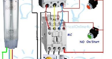
A PF device is a type of relay in which working principles are regarding the phases. This device has 3 points for L1 L2 L3 and when we connect 3 phase power supply to these contacts the relay circuit is active and start testing phases. In this device, a relay is installed and they have three points in which one is common and others are Normally Open (NO) and normally close (NC).
When our main circuit breaker is off, the PF device relay is NC between 1 and 2 Point, and when we switch on our main circuit breaker, the 3-phase supply start to the phase failure device and the device relay energize and make an NC connection between 2 and 3 contacts.
In Case one phase is missing in the circuit, the device will de-energize the relay and it’s made again NO contacts between 2 and 3 points.
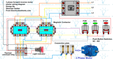
I hope you understood the working of the phase failure relay now let’s talk about the below diagram, in the below diagram I connect a phase failure with a circuit breaker and contactor/motor starter, and overload relay.
In the below diagram, I completely wire a 3-phase motor because if I did not show the complete method and only showed the phase controller then you will not understand completely.

Note due to the wrong connection, the above diagram is an update
In the above diagram, I have shown the complete method of wiring or connection of phase failure relay diagram with circuit breaker, cont actor, overload relay, push-button switches, and electric motor, however, let’s talk about this step by step.
- First of all, do a connection between the MCB circuit breaker and the contactor/motor starter.
- Then Do the connection between the 3 wires between the contactor and the overload relay.
- Then get a three-phase connection for the PF phase control device and connect it as shown in the above diagram.
- Then get a connection L1 point in the PF device and connect to the common point for the relay in PF which is 2.
- After that do the connection between PF point 3 and overload relay NC point 96.
- After getting a connection from the overload relay point 95 and connecting it to the contactor normally open the auxiliary point and red push button which is normally close.
- Then get the wire connection from other connection points of the Red switch which is off push the button and connect to the switch on the push button which green push button which has normally open contacts.
- Now do a connection between the green switch and the cont actor another side normally open auxiliary contacts point and then connect a wire here and provide it to the cont actor coil.
- Now get a connection from L1 which is shown in Red colour and connect to the coil another side as shown in the above diagram.
- Last, provide the incoming supply to MCB (miniature circuit breaker) 3 pole CB and after that switch off the circuit breaker and do connection between three phase electric motor and overload main contacts.
Also, read Below
How to wire 3 phase motor?
How to wire 3 pole MCB circuit breaker?
I hope now you completely understood the wiring of the phase failure relay or connection phase controller, INSHALLAH I will write a more helpful post about electrical technology.
Note that some phase failure relay or phase controller have also a Neutral point and you must provide the neutral to the device. This will highlight or be named with N or mp.
That is wonderful explaining and its totally helpful.
Thank so much
That is wonderful explaining and its totally helpful.
Thank so much
Thanks dear…
very nice & useful.
Thank you dear
I needed diargam with intere wiring
I needed diargam with intere wiring
I think your spelling is wrong plz write again….
This comment has been removed by the author.
Hello bros, thnx for the work you did here. I want to know how you managed to energize the contactor without a neutral (N)??
I mean the contactor coil without a neutral??
Enter your comment…also mi want to know where neutral is
At this juncture in time a "new technology" of aluminum wire was developed, known as AA-8000 series which is the current aluminum wire used today for branch circuitry, however it is extremely rare to find in branch circuit wiring.http://www.envisageonline.com/
the other terminal for the contactor coil is connected to the othe phase that mean the coil works on 380v not 220vac- nazmi ashour
the coil energized on 380v line to line voltage
Thnx….😘 that's Amazing.
Well done 👍👍👍 and God bless you🙌🙌🙌
Thank you very much. This is helpful Please can you write something similar but on wiring automatic transfer switch for Mains and auxiliary power connection three phase
Thank you very much OK very clear
Thank you very much for this explicit explanation. May Almighty Allah rewards you abundantly
You have a good point here! I totally agree with what you have said!! Thanks for sharing your views. hope more people will read this article!!
메이저사이트
경마사이트
This is wonderful website to find blogs on various topics. 토토사이트