Contactor Wiring Diagram For 3 Phase Motor with Overload relay
In the industrial system, we use mostly three phases of electric power for electric induction motors. A single-phase induction motor can not do work as a 3 phase can be done. For 3 phase motor, we use some electrical devices for starting, off, and resetting, the magnetic contactor is one of them that’s why today we disuse contactor wiring with a complete explanation. In 3 power systems, we use some devices between the induction motor and supply which are a CB Circuit breaker, MC magnetic contactor or motor starter, O/L overload relay, and NC, NO push button switches for on/off and reset.
How To Do Contactor Wiring For 3 Phase Induction Motor With 3 Pole Circuit Breaker, Overload Relay, NO, NC Push Button Switches
In this tutorial post, I will tell you about motor contactor wiring and its diagram. But before we will disuse devices and working of these.
3 Pole Circuit Breaker CB
For the 3P power supply, we use a 3-pole circuit breaker for the switching supply. Always use a CB before circuit wiring, from this you can make your circuit safe and we will be able to switch it off/at any time. You can also use 4 pole breakers, which is very best because you can control also the neutral wire.
MC Magnetic contactor
For 3-phase induction motor start/stop we use always MC contact or. It is a type of electric relay which can switch the 3 electric connections easily. I also published posts about motor starter working you can see on the below links.
Click here for more information.
O/L Overload Relay
An overload relay is a protective device that makes safe our electric motor from burning during high current flowing to the induction motor. There are two popular types of O/L relays thermal overload relays and Electronic overload relay. In this wiring diagram contactor, I have shown the thermal overload relay however soon I will make a diagram about the electronic relay.
NC Normal Close Push Button Switch
For motor contactor wiring we use push button switches for switching on/off the motor. NC means normal close which means that this push button is normally in a close circuit and when we push, it makes an open electric circuit. I show NC with a red colour button and NO with Green colour.
For details Click here.
NO Normal Open Pushbutton Switch
The Normal open S is normally in an open electric circuit and if a person pushes this NO it makes an NC circuit. For further information visit the below link.
For more info click here.
MC Motor Starter Wiring Diagram With CB, MC, O/L, NO, NC
The symbol diagram is best but everyone can’t understand it easily that is why I always focus on image+diagram which is easy and simple to understand and good for learning. But you know that this diagram design takes bag time from the time of the symbol diagram. But I love my readers, as I am a student and struggling- for learning. I want to share all things which I learned.
Magnetic contactor relay wiring and circuit breaker, push-button wiring method is simple. And i think that there is no importance to explain more after making a diagram, however, let’s get a short tips journey.
For 3 phase motor controlling diagram and procedure, follow the below tips.
- First of all wire the CB Circuit Breaker but do not switch it On.
- Then Wire push button wiring O/L relay and MC coil, which we can call “small wiring” or “control wiring.
- Then wire the overload relay with MC.
- Then Do the connection between CB and MC.
- Then do a motor supply connection with the Overload relay.
- Then connect the earth-led wire to the motor body.
You can follow the same method as I have shown in the below contactor wiring diagram for wiring 3 phase motor with a circuit breaker, 3-pole motor starter, and overload relay.

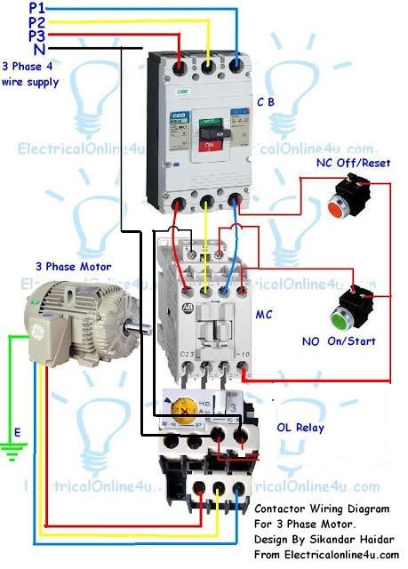
In the above contactor wiring diagram, I have shown a 3-phase 440 volts 4-wire system. I take one phase and neutral wire for the MC coil which is 220V, but always wire your contactor coil regarding coil voltage / current requirements. If the coil required 110V to 120V then provide 110 volts supply and if it wants 380 volts to 440V to energize then connect the same required supply. The coil voltage cheat- is near the coil supply terminal/connection so check it first before starting.
In the overload relay, we have two options NC and NO. When the overcurrent flow from NC points, it makes an open circuit. Which are shown in the above image with 95-NC-96.
If you want to learn from the symbol contactor wiring diagram then click here.
Message :
The above is an example diagram of contactor wiring with an overload relay, and I hope that this diagram helps the newbie very much. But this is only starting and IN SHA ALLAH we will make more best contactor wiring and more tutorials for you.
Stay tuned…. and keep visiting……

4 phase motor controller panel box full wiring diagram need.pls help
Dear IN SH ALLAH i will make complete 3 phase 4 wire system panel box wiring…..
hi,
u added two red wire through nc and no button with the overload. what is that for?
It is not between nc and no. it is in nc to nc and when over current flow the overload relay will make an Normally open connection between these two nc points and current is stop flowing to contactor / stater coil.
Thank you for your most valuable contribution to spreading knowledge. The pictorial wiring diagram is genius. Thank you.
Regards
Deo Winter
hello i have 3 phase wiring in my house , i want co connect a 3 phase contactor in such a way that a hotel type key switch can control the contactor . when the keychain is removed the contactor goes off and power to house is cutoff. will the contacting coil work if one or two phases are off
thanks dear…………
if there wering asked ATS to genset..thanks Sikandar Haidar..!!?
I, love all
Thanks for your love…..
Thanx Sikandar for the valuable information.
can you show a Distribution Board Wiring For three Phase Wiring, with options for a couple 220v single phase connections.
Example. I have a 3phase engine suppling power to a 3phase borehole pump/motor with a switch the one above in your example. But i want some single phase connections on the DB for
my single phase power tools. e.g. grinder,drill and welding machine and light for the pump house. How do i connect up..
Thanx
kgabo
https://svitsensoplanbytrumsense.aliexpress.com/store/410640?spm=2114.12010615/itm2home-3.0.0.633031b9B55K8S
Hi, I enjoyed your work. What is the circuit diagram use to connect dispensing pump in petrol stations ?
Hi, I enjoyed your work. What is the circuit diagram use to connect dispensing pump in petrol stations ?
One, Timothy Obinna
Hi! Great diagram! Thanks! Just one question…how would I wire up 2 on/off stations?
DjazakaAllahu hayran bro ! May Allah bless you for your helping ! Keep it going. As-Salamu aleykum from Turkmenistan.
Hey, this day is too much good for me, since this time I am reading this enormous informative article here at my home. Thanks a lot for massive hard work. irf540 replacement
where does it goes those two red wires form the relay
It's good to know what you guys are doing in the Electrical field. It's going to us from those quack connection that is causing most accidents
A very excellent blog post. I am thankful for your blog post. I have found a lot of approaches after visiting your post. source
Very nice post. I just stumbled upon your blog and wished to say that
I have really enjoyed browsing your blog posts. In any case I'll be subscribing to your
feed and I hope you write again very soon!오피
Thanks for sharing this information. I really like your blog post very much. You have really shared a informative and interesting blog post with people
카지노사이트
wep
I think a lot of articles related to are disappearing someday. That's why it's very hard to find, but I'm very fortunate to read your writing. When you come to my site, I have collected articles related to 크레이지슬롯.
Are you the one who studies this subject?? I have a headache with this subject.우리카지노Looking at your writing was very helpful.
you will need support or suggestions, write me privately.
I interested in your implementation/use case.
the best kera4d
Togel2win
They have one of the widest ranges of non-card payment options on the market with local deposit options and e-wallets like PayPal merchant portfolios for sale
This website certainly has all of the information and facts I needed concerning this subject and didn’t know who to ask. 바카라사이트
Genuinely when someone doesn’t understand afterward its up to other viewers that they will help, so here it takes place. 온라인바둑이
This article is very helpful and interesting too. Keep doing this in future. I will support you 스포츠토토
Keep up the excellent work and delivering in the group!
야설
Greetings, You've worked really hard. I will burrow it and by and by recommend to my companions.https://www.full-service-janitorial.com/ IS a excellent cleaning company
Hello, i think that i saw you visited my site this i came to “return the favor”.I am trying to find things to
enhance my web site!I suppose its ok to use a few of your ideas!!
야설
This is really helpful post and very informative there is no doubt about it. it’s awesome dude I found this one pretty fascinating and it should go into my collection.
마사지블루
Wonderful post with amazing article. This post was very well written, and it also contains a lot of useful facts that is useful in our life. Thanks
야설
I got this site from my friend who shared with me concerning this
website and now this time I am visiting this website and reading very informative articles or reviews here.
마사지블루
It has fully emerged to crown Singapore's southern shores and undoubtedly placed her on the global map of residential landmarks. I still scored the more points than I ever have in a season for GS. I think you would be hard pressed to find somebody with the same consistency I have had over the years so I am happy with that. 메이저토토사이트
마사지블루Fabulous, what a blog it is! This web site presents helpful information to us, keep it up.
I simply wish to give an enormous thumbs up for the great information you will have here on this post. looking for good and trusted sports betting site?click the link here
건마탑
Thanks for taking the time to discuss that, I feel strongly about this and so really like getting to know more on this kind of field. Do you mind updating your blog post with additional insight? It should be really useful for all of us. high voltage ceramic capacitors
Thank you for sharing this information. I read your blog and I can't not stopped my self to read your full blog. Again Thanks and Best of luck your next Blog in future.
바카라사이트윈
Nice one! thank you so much! Thank you for sharing this post. Your blog posts are more interesting and impressive.
바카라사이트윈
This is one of the best website I have seen in a long time thankyou so much, thankyou for let me share this website to all my friends
토토사이트링크
kera4d
kera4d
kera4d
kera4d
kera4d
Togel2win
Togel2win
Togel2win
Togel2win
Togel2win
kera4d
Togel2win
I was impressed by your writing. Your writing is impressive. I want to write like you.안전놀이터 I hope you can read my post and let me know what to modify. My writing is in I would like you to visit my blog.
keonhacai
betflix our online slot game website. It's an easy place to bet, รับเครดิตฟรี
Try Free Slots. https://pgslot-games.com/
Try Free Slots. https://pgslot-games.co/
betflix You will get access to the hottest new and trending slots games ฝาก-ถอน
Traditional bookstores have always existed on high streets, but in the digital age, the internet is proving to become a serious competitor to traditional brick and mortar stores. This article examines both sides of the coin and provides an appropriate insight into the phenomenon of shopping of books online. 메이저사이트추천
fhh
Interesting article thank you for sharing check article here Securities Classaction Directory
Pingback: Shunt Trip Breaker Wiring Diagram - Electrical Online 4u - All About Electrical & Electronics