3 Phase Current Transformer Wiring Diagram
3 phase current transformer wiring diagram for 3 phase load (ampere) testing. As you know that we use the current transformer to measure the current. For testing the current (ampere) running to load we use two types of amp meters. Which one series type is wired in series between load and supply. And 2nd is a current transformer type which is wired with a current transformer to measure the current. We can wire a current transformer for a single phase and also for 3 phase. The current transformer is always used for line ampere testing. For 3-phase system ampere testing every Line has its own current transformer. And these current transformers are further connected with a 3-ampere meter or one-ampere meter and ampere testing selector switch.
For better understanding also read below
How to wire current transformer with digital ampere meter
Ampere meter selector switch wiring with current transformers
How to 3-phase current transformer wiring diagram with ampere meter
Note that if your ampere meter is 100/5A then used only 100/5A ratio current transformer. In the below 3-phase current transformer wiring diagram with amp meter. 3 CT coil and Amp testing meters are shown. The current transformer wiring for each meter.
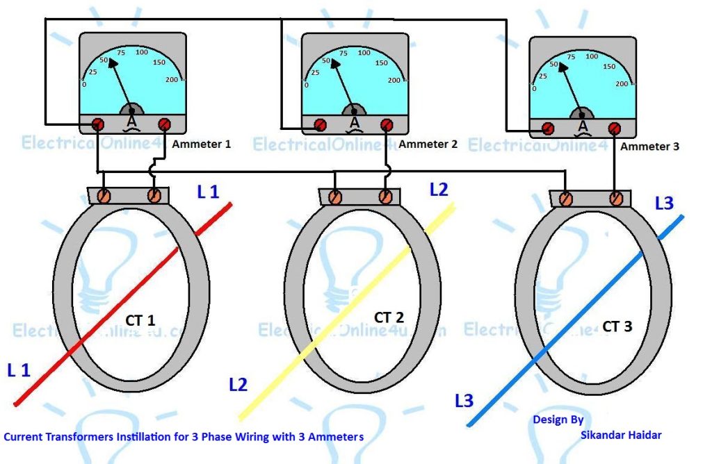
You can wire the current transformer for a three-phase system as shown in the above diagram. However, if you want to test 3 phase ampere with the only one-ampere meter. Then use an ampere selector switch with the current transformer. For that, you need to wire all 3 current transformers with an amp selector switch. And from the selector switch, the two-wire supply will go to the ampere meter. From the selector switch, you can test at each line(phase) ampere.

Why is the one point of ammeter/ct connected together with each other.
This is common
Amazing post, Which you have shared here about the 3 Phase Current Transformer Wiring. Your article is very informative and nicely describes the process of 3 Phase Current Transformer Wiring. I would like to thanks for sharing this article here. residential electricians near me
WHAT IS COMMON
https://www.kidstoys9.com/2020/01/touch-switch-circuit-using-transistor.html
Thanks for picking out the time to discuss this, I feel great about it and love studying more on this topic. It is extremely helpful for me. Thanks for such a valuable help again. ground fault current transformer
Watch and Download world's famous drama series Kurulus Osman in English on link below
👇
Kurulus Osman in English
📢Get free .com domain name and start your own website
Free .com domain name
Crypto trading online course
Join on link below
Crypto quantum leap
📒 Read Home doctor book online
Then you will be a doctor for your family
Home Doctor Book
💰Create own NFTs and earn 1000$
Complete guide
Create NFT
Join online YouTube course
And be a professional YouTuber
Tube Mastery and Monetization by matt
🦷Steel Bite Pro
Best product for
Teeth pain, cavities,teeth whitening and other oral health issues with money back guarantee
Steel Bite Pro