Ammeter Selector Switch Wiring Diagram
With a new three-phase diagram I am here, in this post, I am writing about the ammeter selector switch wiring diagram in which I have shown the complete method of ammeter selector switch connection with the current transformer. I also write and publish posts about ammeter and current transformers. And if you don’t read our last post about CT coil and ammeter then kindly read these first. I provide a post link below after also reading the tag.
Update
Now I am capturing some images from an electrical panel board where the ammeter selector switch was installed by my teacher Mr Fazal Mana who has a big experience in the motor winding and electrical panel board installation and making.
As you know that an ammeter selector switch makes it easy to test the three-phase ampere and load testing
In the below image a panel have only 4 places for electric panel meter installation and if we install the three-meter for voltage testing then we have only one place for an ammeter and we don’t have a place to install the three ammeters, so the ammeter selector switch makes easy to test and measure the all phases L1, L2, L3 amperes with on panel ammeter by using the selector switch.

In the above image, I have shown the three voltage panel meters and one ammeter with a selector switch, now let’s see the wiring connection image of these meters. I know that the wiring connection is not too clear to understand, however, the reason for the image publishing is to learn about the method and wiring connection clearness.

Now lets the back side of the panel meter selector switch with a wiring connection.

In the above images, I showed light indicator and voltage and amp meter wiring, so the below links help you to complete understanding.
Light indicator wiring of 3 phase
How to install and wire voltage meter for three phase
Ammeter Selector Switch Wiring Diagram with CT Coil (current transformer) and Ammeter Connection
Before we start talking about the main diagram and main topic, first we disuse some things which are related to this post. I publish a post about CT wiring and installation and you will learn by reading the below post.
Also Read:
How to connect CT to Ammeter?
How to wire a digital amps meter with a current transformer?
How do install CT coils for Three phase in the Main Power panel board?
So what is an ammeter selector switch? and why we use this for ammeter and ct coils where we can do this without a selector switch. As you know that we install three CTs (current transformers) for measuring three-phase ampere (load) and these three ct required three ammeters which show the amperes to us. So the ammeter selector switch is a selector switch from which we can do this work with one ammeter/ampere meter and we don’t need to install three ammeters. The selector switch changes the ct connection to the amps meter.
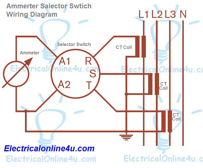
In the above diagram, I show the three-phase four-wire supply with three CT coils. In the selector switch connect all CT Coils connection to R, S, T. and get supply From A1 and A2 for the ammeter. Note that this ammeter switches the front menu available in different names such as 0-1-2-3, L1-L2-L3 and R-S-T. Note that in the above diagram, I connect all current transformers with one wire with a point which I have shown with the earth symbol and if you don’t connect this common wire to A2, the connection and ammeter will also work properly.
This is too simple a wiring connection and no need to explain more, however, if I find any image of the ammeter selector switch with which the connection point is shown clearly then I will design another diagram. However, the easy way is to make your own 3D switch image in which connection contacts are shown clearly When I have done this, I will publish it. Now I hope you understood this ammeter selector switch wiring diagram and IN SH ALLAH soon I will write about voltmeter selector switch wiring.

Hi Mr.
if i want to add digital power meter, can i loop series s1 s2 from the selector switch?
Thank you for this write-up. I am still learning and have a current project that this will help. I do have a question. If I have 2 ct coils, wired like you show, is there a way to add jumpers so the last posion of the switch can combine the 2 ct coils? I have ct on l1 a ct on l2 and want l1+l2 on last position.
This comment has been removed by the author.