Voltmeter Selector Switch Wiring 3 Phase 4 Wire System
As you know that last time I published a post about the voltmeter selector switch wiring which was about the three-phase voltage measuring and in which we did not talk about the neutral connection. In this post, I also write about voltmeter selector switch connection wiring but the last time I talk and publish a diagram about the 3 phase in this post you will learn how to measure 3 phase 4 wire system voltage using a voltmeter selector switch and a voltmeter.
Voltmeter Selector Switch Wiring Connection For Three Phase 4 Wire system
Last day I am working on a panel board with my teacher Mr Fazal Manan and we wire a voltmeter selector switch in the power factor panel board. We also install the ammeter selector switch in this panel board.
And When we have done this work, I capture some images related to this post, from these images you cannot easily learn the wiring connection but you can learn the installation or get an idea of installation. And I hope from these images you will be able to select the correct place for this switch and you will also see its back side wiring connection images below. You will see the clearness and level of work and if you follow the same method, your work will look very handsome and awesome.
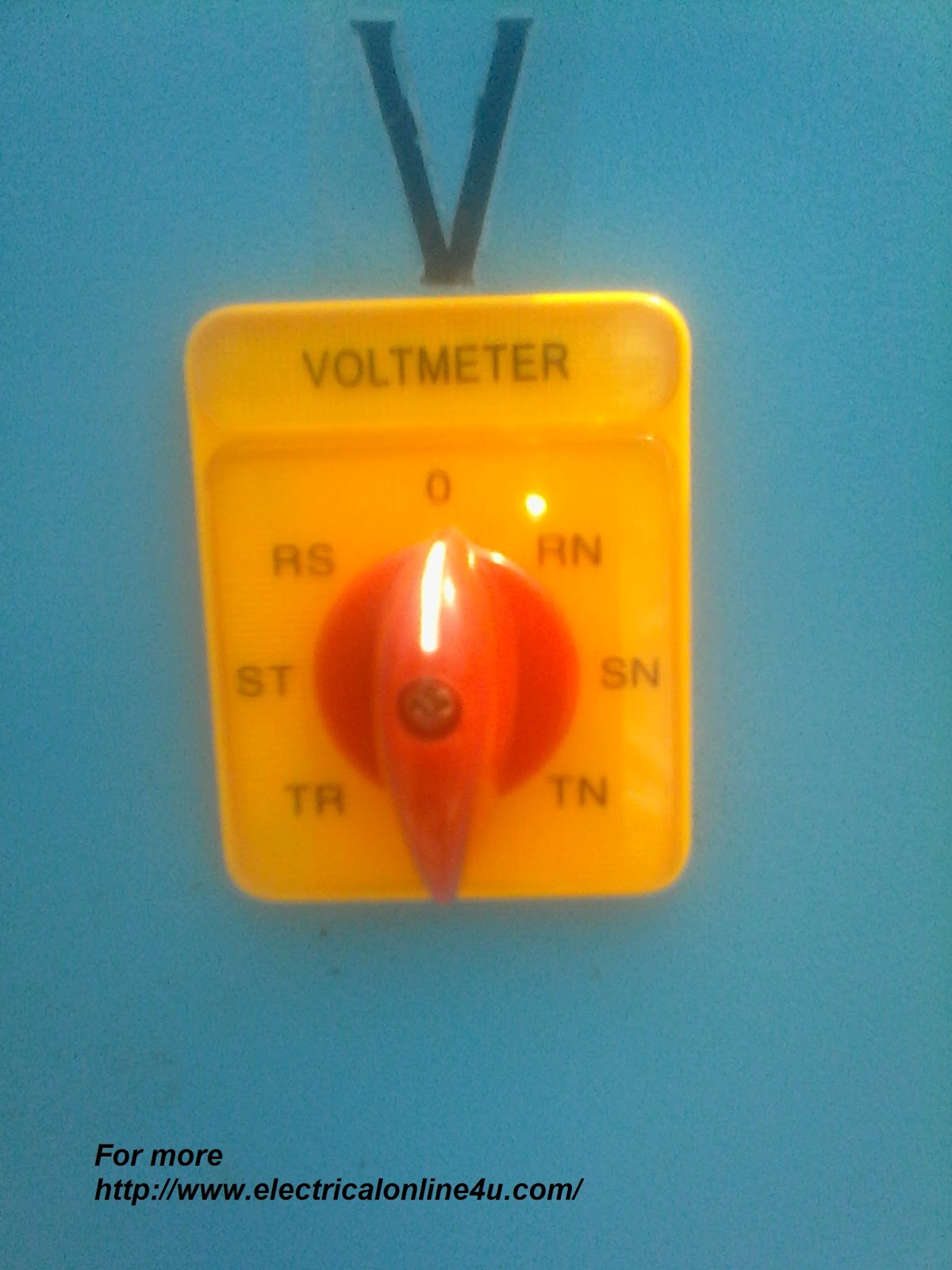
From these images you will learn the installation and correct place for the selector switch, but what about the wiring connection? Be cool I also share the connection diagram for the voltmeter selector switch wiring for the 3-phase 4-wire system. With these images I also guide you on the wiring connection, first, we start with its front view which is the voltmeter selector switch escutcheon plate which is shown below. In RS, ST and TR options for testing voltage between two phases. 0 for off and RN, SN and TN for voltage measuring between one phase and neutral.
So what about the wiring connection, this selector switch wiring is too simple and easy, as you know that we use R, S, and T for three-phase and N for neutral. So this selector switch has terminals with the name V1 and V2 which are for the Voltmeter and R, S, T for 3 phase power supply where we connect the three-phase wires with the R, S, T terminals in the back side of the voltmeter selector switch and N for neutral where we connect the Neutral wire.
You can see the back-side wire connection of the selector switch in the below images.

In the above image, you can see the S, R and other connections, but all connections are not clearly shown, however at last I am sharing the diagram which can help you to fully understand.

In the below image, you can see the V1, V2, T and N connection point areas.

I hope you got some great knowledge from the above images and article but this is not complete without a complete volt meter selector switch diagram. The below diagram shows the complete method and wiring connection of the selector switch for 3 phase 4 wire system. (Note that this diagram I took from a book, and Soon I will design a diagram for this with digital voltmeter installation).
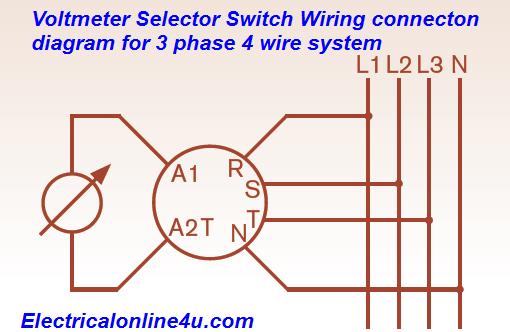
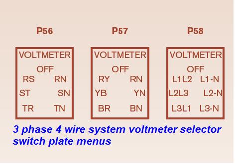
The above diagram is about the model of the C176 selector switch, and it’s available in different escutcheon menu plate which is shown below.
Also, read below
Ammeter selector switch installation for 3 phase
V Meter selector switch installation for three phase
So How A voltmeter Selector Switch works for 3 phase 4 wire system, and Why do we use it?
The major use of the voltmeter selector SW is to measure the voltage of the 3-phase 4-wire system in between two phases and phase neutral by using only one voltmeter at the same time.
E.g example ” we get first one menu from about menus which P56, in the centre, we have OFF option and when the knob on offside the voltmeter will be off, So we named our phase with R, S, T and N for neutral.
So if the knob on RS the voltmeter will show the voltage between the R and S phase, and if the selector switch knob on the ST, this will show the voltage between the S and T phase and on TR this is will show the V between the T and R Phase. So this is for 3 phase now come to the test the voltage between neutral with all phases.
So if the knob is on RN the volt meter will show the volts between the R phase and neutral and if the knob is on SN the V meter will show the voltage between the S phase and neutral. And If we set the knob on TN, it’s will show the volts between the T phase and neutral.
In short, the voltmeter selector switch is a switch from which we can test the voltage of 3 phase 4-wire system using one voltmeter in a very short time and we don’t need to install voltmeters for all phases.
I hope you got some knowledge from this voltmeter selector switch wiring diagram for 3 phase 4 wire system, not that you can also use the voltmeter selector switch for three-phase only but if you have neutral available in the circuit then the better option to use it for the 3 P 4 wire system and it’s is made for this work.
You have shared very precious information.
http://google.co.uk/
WOW! What a decent combination of Voltmeter Selector, Switch Wiring and Instillation For 3 Phase 4 Wire System. Can you share with us step by step installation of a solar system's electrical wiring system for home and even for a small commercial project.
https://www.electricalwarehouse.com/
Dear i love to tech you online which i learned.
Thanq very much sir for your valuable information…. I want to know about electrical power production, transmission, distribution
V1& V2 with whom should i connect?
Hi there, this weekend is good for me, for the reason that this time i am reading this enormous educational piece of writing here at my home. paypal login my account official site
We put in an abundance of ninety hours on the vessel generator in just five days; time for another oil change!Installateur zonnepanelen
I had a forty year amortization, and incredibly did not want being paying this mortgage until I retired. mortgage payment calculator canada However, you're adding the same amount that you would have paid under an accelerated biweekly plan. mortgage calculator canada