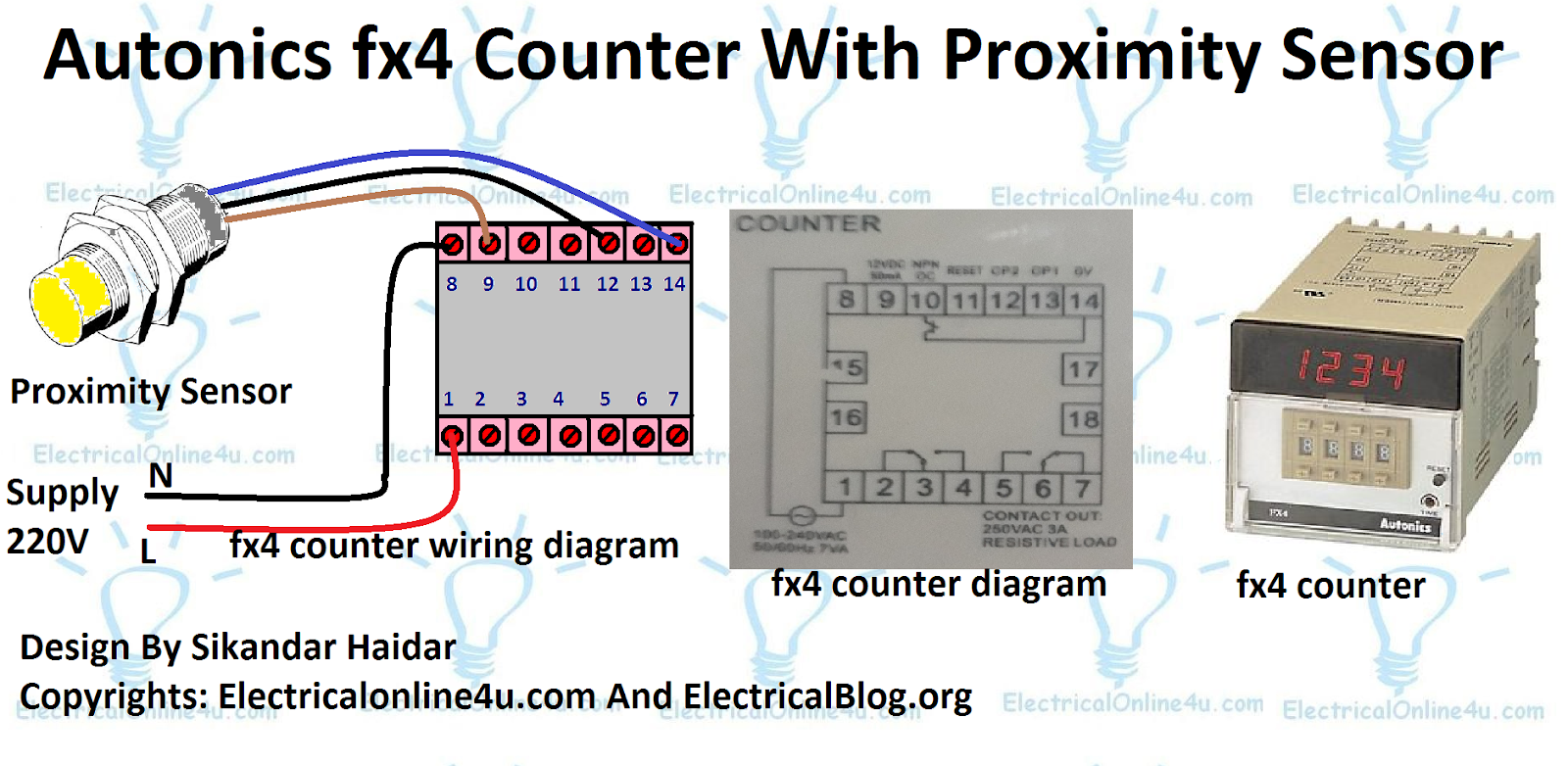
Autonics Fx4 Counter With Proximity Sensor Diagram
Autonics Fx4 counter with proximity sensor diagram, today I will share the diagram of the fx4 counter which a digital counter made by the autonics company. This counter has a digital display and 8 switches for increasing or decreasing the counting. This counter is used with a proximity sensor.
In the fx4 counter, we have 14 terminals for connection. In which 1 and 8 terminals for AC supply 220 VAC. You can also use a 7 VA transformer to provide the electric power to the autonics fx4 counter. The 9 terminal is for 12 Volts DC 50ma and 12 and “13 terminal” for CP1 And CP2 for the sensor sensing wire.
The 14 terminal is for O volts DC and the negative terminal is for the proximity sensor. In the proximity sensor, we have 3 wires. The brown colour wire for 12 Volts or 24 Volts DC. The blue colour wire is negative and the black colour wire is for sensing.
Autonics Fx4 Counter Connection with Proximity Sensor Diagram
Below, I have shown the complete fx4 counter wiring diagram with the connection of the proximity sensor. Also, I have shown the AC supply connection with the counter.

Am requesting for clear diagrams
It’s actually a cool and useful piece of info. I am glad that you just shared this useful info with us. Please keep us up to date like this. Thank you for sharing. https://royalcbd.com/product/cbd-roll-on-gel/
Plzzz diagarms for clear pics