Submersible Pump Control Box Wiring Diagram For 3 Wire Single Phase
Today I hear to write about the submersible pump control box wiring diagram, in this post you will completely understand the 3-wire submersible pump wiring diagram which is a single-phase submersible pump motor. Why we called a single-phase submersible motor a 3-wire submersible, we also know that we have two wires in a single-phase power supply.
As you know that we have two types of winding in a single-phase motor and these coils have also two starting and finishing ends, So we connect the one-one end of each coil and make a common point which know also with the name as the common point. And the other ends are called starting and running terminals or connections. So we have 3 wire terminals or wire which out from the motor, that’s why we called this 3 wire motor.
In the post, you will completely learn about the single-phase submersible pump control box wiring diagram, and this diagram is not too hard to understand like their own diagram which is mostly available on the control box backside.
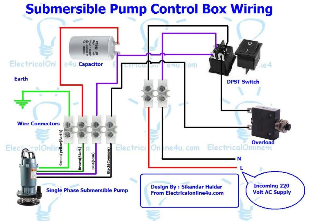
Single-phase submersible pump control box wiring diagram – 3-wire submersible pump wiring diagram
In the submersible pump control box, we use a capacitor, a resit-able thermal overload, and a DPST switch (double pole single throw). The wiring connection of the submersible pump control box is very simple. Here is the complete guide step by step.
- First of all switch off the main circuit breaker in your distribution board, for that reason that you can work safely and protect yourself from electric accidents.
- Then connect the supply to input wire connectors.
- After that get the connection from wire connectors and then connect your neutral and Line wire (hot wire/phase) to the double pole single throw switch as I have shown in the below diagram.
- Then get a hot wire connection from the DPST switch and connect to the resettable thermal overload protector. And form overload protector connects this (black wire) to one of the output wire connectors.
- Now get your neutral wire (blue) from the switch and connect to the capacitor, and form the same terminal of the capacitor and connect it to one of the output connectors.
- Then connect a wire from another free side of the capacitor terminal and connect to one of the out wire connectors which I have shown with red or brown colour in the diagram.
- In 1 number connector connect your ground or earth wire as I have shown in the diagram with green colour.
First, if you know about the starting, running and common wire then connect it box connector as I have shown in the below single phase 3 wire submersible pump box wiring diagram.
Now if you did not know about the star, run and common wire in your pump motor then follow the below compressor terminals identifying tutorial and same follow the steps to find out identify submersible pump wires start, run, and common. (Note that identifying compressor terminals and submersible wire method is the same)
Also, read
How do identify start, run, and common in a single-phase motor or compressor?
How to control a single-phase motor using a circuit breaker?
How to wire resettable overload?
How to control and wire a single-phase motor with a contactor?
In the above wiring diagram, I have shown the complete method of submersible pump control box wiring and installation diagram. Now if you have any questions regarding single phase submersible pump starter wiring diagram then you can use below comment section.


concept is good.
I would like to have circuit with contactor , Ammeter voltmeter, starting switch with indicator
WHAT SIZE CAPASITOR SHOULD BE USE FOR 2,2HP MOTOR
Very good
Another great idea to increase our knowledge.
thank you sir
The circuit did now show any disconnect for the starting winding.
Minimal Gigantic vcma-15uls knocks out consist of a tension resistive which assist these folks complete likewise perfectly while in the high-pressure and low-pressure spots. All these as well develop the advanced level professional advices. On the flip side these are typically affordable plus vigor powerful. look at this site
Thanks a lot for your effort.
You have such great skills of writing blogs and knows how to influence the audience just as Asia Airblast Pte Ltd knows there advanced blasting machines make them different from others.
This could be furthermore a reasonably great article that people definitely valued examining. Certainly not each day that benefit from the probabilities to locate a item. best well pump
Designers at that point concocted a radial fly siphon. Other than having all the segments of a self-preparing divergent siphon, engineers included a jolt shallow well fly. Slurry Pump
Best product
https://youtu.be/RNKDTdLu_rY