Voltmeter Selector Switch Wiring Diagram For Three Phase
Last time we talk about selector switches and I explain selector switch wiring connection and installation for the ammeter and with current transformers. Now in this post, I am writing about the voltmeter selector switch wiring diagram for three phases. As you know that if we install the three voltage meters for 3 phase then it will be a big loss of money.
But we also need to measure and test all phase’s voltage. So if we install a voltmeter selector switch then we can measure the voltage of all phases with one voltmeter. So we don’t need to install three voltmeters for 3 phases and we can save a big money by using the selector switch.
Also, read
How do install and wire the ammeter selector switch for 3 phases?
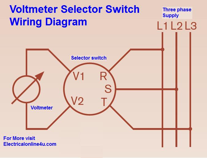
Voltmeter Selector Switch Wiring Diagram For 3 Phase
The wiring connection and voltmeter selector switch wiring diagram are too simple and the connection is the same as we do for the ammeter selector switch, same we connect the L1 L2 and L3 supply connection to R, S, T. And get connection for A1 and A2 to voltmeter as shown in above voltmeter selector switch wiring diagram.
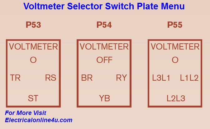
The above diagram, I get from an online book which I share with you in this post. The voltage meter selector Escutcheon Plate is available in three menu types, and you can test and measure voltage between two phases by using the knob. These plate menus are available in (0, TR, RS, ST), (Off, BR, RY, RB) and (0, L1L3, L1L2, L2L3). You can see it below.
I hope you enjoy this post and learn the voltmeter selector switch wiring and installation from this post. Share this post with your friends and like us on social media.