Forward Reverse Motor Control Diagram For 3 Phase Motor
Forward reverse motor control diagram. This post is about the controlling and wiring diagram of 3 phase motor forward reverse motor starter. In this post, you will complete learning about the forward reverse three-phase motor controlling starter diagram.
In the 3-phase motor forward reverse starter wiring diagram. I showed the 3 poles MCCB circuit breaker, 2 magnetic contactors, normally open, normally close push button switch, thermal overload relay, 3 phase 4 wire system supply, 3 phase motor with connection, trip indicator light, etc. In short, this is the complete guide to forward reverse starter wiring and installation.
Forward Reverse Motor Control Diagram for Three-Phase Motor
For a three-phase motor forward reverse control circuit. We use 2 ‘magnetic contactors’ as a forward reverse switch. Here I showed the forward reverse wiring diagram. In the diagram, I connect the incoming three-phase supply L1, L2, and L3 to the MCCB circuit breaker (moulded case circuit breaker). And from the MCCB breaker, I connect the supply to both ‘magnetic contactors’.
Here the L1 is connecting to both contactors’ first terminals. L2 wire connected to both ‘contactors’ 2nd terminal. And L3 wire connected to both ‘contactors’ 3rd terminal.
But the out connection is different. Where L1 is connected to the T1 terminal and connected to the T3 terminal in the 2nd magnetic contactor. The L2 is connected is both contactors in the same terminals (T2). The L3 is connected to the T3 terminal in the first contactor and the 2nd contactor in the T1 terminal.
After that, the three-phase supply goes to the thermal overload relay and from the thermal overload relay, the soppy goes to the 3 phase motor connection plate and is provided to 3 phase motor. Here I have shown the forward reverse motor control diagram for 3 phase motor.
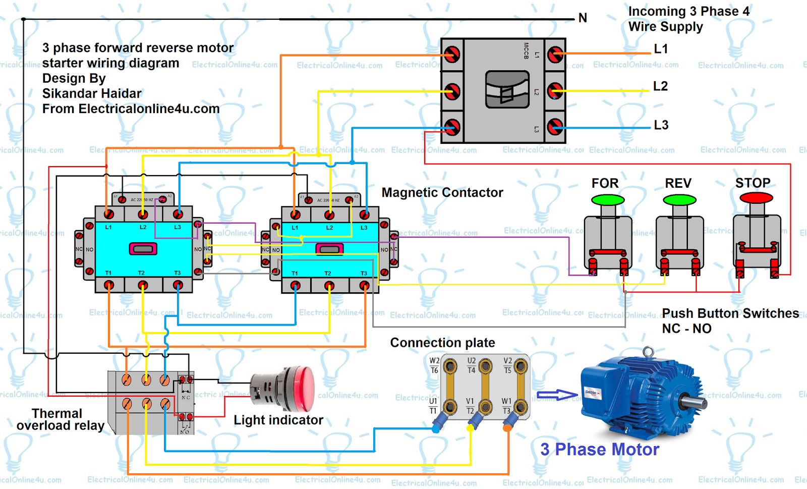
Now come to the controlling wiring. Here I had shown that both contactors are 220 VAC. This means that the contactors also required the neutral wire.
In the above 3-phase motor forward reverse wiring diagram.
The neutral wire first goes to the thermal overload relay NC contacts and the light indicator. From the 2nd thermal overload relay Normal close contacts the supply goes to both contactors coil contacts/terminals. And connect to both magnetic contactors A1-A1 terminals.
After that, the L1 wire is going to the thermal overload relay NO contacts and from the 2nd thermal relay NO contacts terminal the wire goes to the Light indicator. So if the motor trip the light indicator will glow up.
For the Normally close (red/stop) push button switch the supply comes from the L3 in the red colour wire. And from the NC switch, the wire goes to both NO switches (forward and reverse push buttons). And from here the Hold current wire goes to both magnetic contactors NO auxiliary contacts(connection points).
From the forward push button switch, the (touch current) supply goes to the 2nd contactor NC auxiliary contacts and from the auxiliary contacts, the wire goes to the first magnetic contactor NO auxiliary contacts terminal and coil A2 terminal as shown in the above forward reverse motor control diagram.
The same wiring connection is done with the reverse push button switch. The touch or starting current goes from the reverse push button and connects to the first contactor Normally close the auxiliary contact/terminal and from the auxiliary contacts, the wire goes to the 2nd contactor Normally open auxiliary contacts/terminal and contactor coil A2 terminal as shown in the above diagram.
In the above connection, if one contactor is energized then another contactor will not be energized at the same time.
Also Read:
How to wire DOL Stater animation
3 Pole – 4 Pole MCCB Wiring Diagrams And Installation
Digital Ammeter Wiring With Current Transformer – CT Coil
Message:
I hope the above forward reverse motor control diagram / 3-phase motor forward reverse starter wiring diagram helps you to understand this connection. Now if you have any questions or any suggestions then you can use the below comments box. I hope you will share this post on social media.

kindly share which software have you used for it.
kindly reply on
rashid.akbar@ial.com.pk
thanks
I wanna get application
This comment has been removed by the author.
the only thing missng is holding contacts for maintaining….
Do have a diagram of this motor control?
Please I don't have the Normally close on my contactors so please where can I connect it? Thank you
Good day! I could have sworn I've been to this website
before but after reading through some of the post I realized it's new
to me. Nonetheless, I'm definitely glad I found it and I'll be bookmarking and checking
back frequently!강남오피
A very awesome blog post. We are really grateful for your blog post. You will find a lot of approaches after visiting your post. spy phone
Incredible post I should state and much obliged for the data. Instruction is unquestionably a sticky subject. Be that as it may, is still among the main themes of our opportunity. I value your post and anticipate more. 메이저저사이트
Pingback: Forward Reverse Starter With Timer 3 Phase Motor Wiring Diagram - Electrical Online 4u - All About Electrical & Electronics