Shunt Trip Breaker Wiring Diagram Explanation
As you know Safety is important in electricity works. Today I am writing about the shunt trip breaker wiring diagram which is related to the safety and protection of electricity. As you know that electricity is dangerous but it’s become more dangerous when it’s upgraded from 220 volts to 3 phase 440 volts. As you that mostly we use 3 phase system in industrial states where we can not protect our electrical distribution using RCD (residual current device).
In Single phase wiring or house wiring, we use an electric power supply between phase and neutral which can be controlled by using a simple double pole RCD Breaker. But When it’s come to high-load places or where we use the three-phase supply then use an MCCB (module case circuit breaker) Shunt trip circuit breaker with an emergency push button switch which we know better with the name of EPO (emergency power off) button.
Shunt Trip Breaker Wiring Diagram with EPO Button.
In this post, I am just telling you about the wiring of a single EPO button with a shunt trip MCCB breaker. In an industrial state, the Electric operator’s duty is to operate the machinery and his duty is on the front of the Main panel board.
Now if a short circuit is done in an electrical installation or other electrical accident, the operator can easily push a small push button switch and the all-electric power supply will be powered off. If we compare it with switching off the main circuit breaker then it will get more time.
Among the advantages of a shunt trip breaker, the most important thing is that we can install the emergency switch (EPO) anywhere, from where can easily push the button or where the push button is near to us.
One thing more is that we can install more than one EPO button for one breaker and every button will work the same. However, in this post shunt trip breaker wiring diagram I show only one EPO button and INSHALLAH in the next post I will show you the installation of multi EPO (emergency power off) buttons for a single shunt trip MCCB breaker.
Also, read below
How do wire 3 or 4-pole MCCB Breakers?
How to wire RCD Breaker?
How earthing system works?
How Shunt Coil Work
In simple words, a shunt trip is an electromagnetic coil which makes a magnetic field by providing an external power source. In the coil a moveable rod is fixed with a spring and when we provide the supply
The shunt trip moveable rod hit the tripping point or disconnecting point of the circuit breaker internally and the breaker becomes off or trips.
In the MCCB circuit breaker, we have a pushable button or place which is named “push to the trip” and when we switch on the breaker and push this button the breaker becomes switched off and trips due to pushing this button.
The shunt trip coil rod pushes this point internally when the shunt coil is operated.
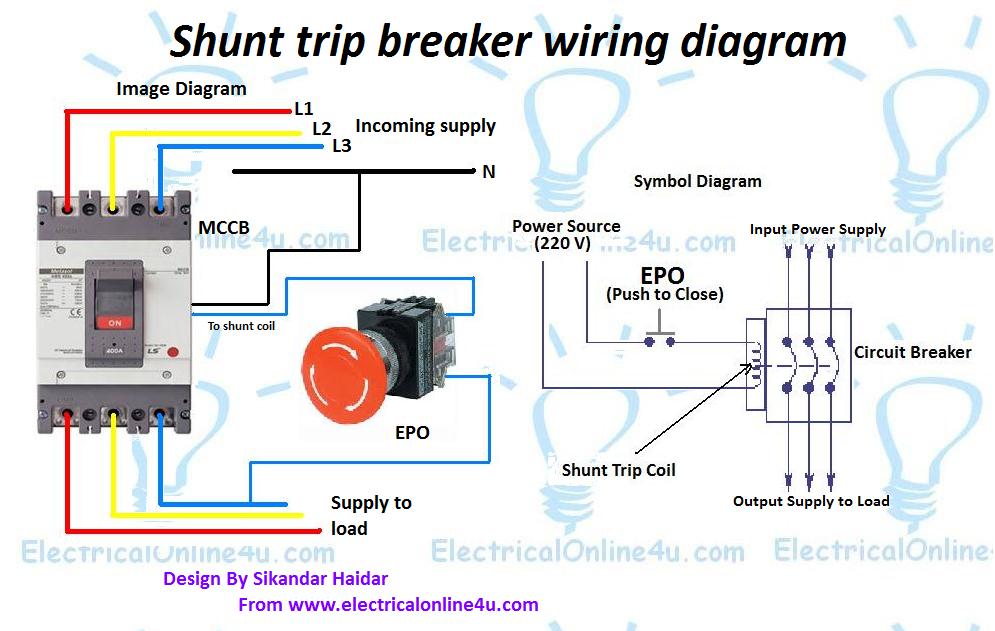
Here are some images of shunt coils and after that, we will discuss the shunt trip breaker wiring diagram with an image + symbol diagram.


Now let’s how to wire the shunt trip device (accessory), it’s too simple as I have shown in the above shunt trip device images that a shunt coil has only two wires, just like a magnetic contactor or magnetic relay coil. But you must provide the power source regarding coil-rated volts. You can find out the rate coil label on the shunt coil, circuit breaker or on the shunt trip coil.
But the question is how to wire it. And the answer is that “it’s also too simple”.
We use a push button switch for the shunt coil which we know by its short name “EPO” which I discuss in my above words.
In the EPO switch, we have four terminals of which two are Normally close to each other and the other two are normally open.
So we need to provide the supply / current to the shunt trip device circuit breaker when the emergency moments come.
I.e example ” if we have a shunt trip coil which operates on 220 volts, so we need to provide the 220 volts AC current to the shunt trip coil to operate or to trip the breaker in an emergency time. So our neutral will be connected directly to the shunt tripping coil and Phase (hot wire) will be connected to the coil another side through the EPO push button switch normally opens contacts.
So the EPO switch will be normally open and when we push the switch in emergency time the switch normally opens contacts will make a close contacts connection and the hot wire current start flowing to the coil and complete the circuit because the neutral wire current is already connected to the coil. So the coil will make a magnetic field and push the rod, the rod will press the trip point and the breaker will disconnect the power supply to load.
Here is the complete explanation of the shunt trip circuit breaker wiring diagram which helps you understand completely.
What is the purpose of a shunt trip circuit breaker
The main purpose of a shunt trip breaker is that we can easily switch off the main circuit breaker from our nearest place in a short time and can save us from electrical accidents.
Final words
To wire, a shunt tripping breaker follows the below steps.
- First of all wire your Circuit breaker.
- Then connect the neutral wire to the shunt trip coil.
- Then connect the Phase (hot wire) to the EPO button normally open contact.
- Then get a connection from EPO to another side of the normally open contact and connect to the shunt trip coil.
Hi, I have a three phases circuit breaker, with 4 incoming cables and 4 cables to load (even the N cable is connected through the circuit breaker). Is it correct to connect the shunt trip to the phase and N in the load side of the circuit breaker?
thanks this is good blog. https://krmlight.com/shunted-vs-non-shunted/
One thing more that we can *install more *than* one EPO *button.