How To Make A Series Testing Board Diagram
This post is about the series testing board which we can use in those places where we did not available another electrical testing device. It is the oldest but one of the best methods of testing electric appliances or devices. In many places where we do have not a multimeter and we are required to test an electric motor or another connectivity test then we can use a series testing board which is very simple to wire or make however, we can not test all things but the necessity is the mother of invention.
How To Wire A Series Electric Testing Board
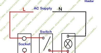
To wire a simple testing board, you will require an electrical outlet or 2-pin socket, an incandescent light bulb and a holder. To wire the electric testing board, first of all, connect the neutral wire to the lamp holder and then connect the phase wire to the outlet terminal and then connect a wire between the socket/outlet and holder as shown in the below diagram.

Advantage And Uses of Series testing board
There are many advantages and uses of the series board some are below.
We can make this board any time within a small time.
We can use it for connectivity tests.
We can use it for short-circuit tests.
We can find out the shortage in any electrical appliances.
We can do a connection of a 3-phase motor in the start, delta.
We can find out the start and run common connection in electric motor or compressor.
We can test the conductor by using this board.
The uses and advantages of a series testing board in unlimited and we can use it for many things. This is a simple diagram of the series board but we can not test low-resistance appliances / electrical devices, however, my incoming post will be about the series board for low-resistance appliances testing.

nice
thanks dear……..
It does not matter if it is a large domestic appliance or a small one, very often people are prepared to order on faith via a good online electrical shop.this site
Nice
Very informative article, Which you have shared here about the series testing board. After reading your article I got very much information about the process of making series electric testing board and it resolved many of my doubts. Thanks for sharing this article here. test & tag adelaide
I read your post and got it quite informative. I am impressed by the details that you have shared in this post and It reveals how nicely you understand this subject. If anyone interested to know more about the electric test and tag prices, Visit servicecorptestandtag
You have shared a nice article here about the Series Testing Board. Your article is very informative and useful to know more about the process of making Series Testing Boards. Thanks for sharing this article here. electrician companies near me
I really enjoy simply reading all of your weblogs.test tag perth
This is extremely fascinating substance! I have completely delighted in perusing your focuses, I've read in a very long time. The amount of information in here is stunning, as we provide Tag And Test Melbourne at an affordable price. for more info visit melbournetestingandtagging.com.au
How about if I connect phase directly with bulb holder and connect neutral with socket….?
You've created an excellent essay. Your essay gave me some unique and useful information. Thank you for bringing this article to our attention. Electrical Outlet Boxes
You've shared some excellent material. I'm grateful for this post because it contains a lot of useful information. Thank you for sharing this piece of writing. roxtec mct installation manual
I read your post and this blog is very good. You have provided good knowledge in this blog.This blog really impressed me. Thank you for sharing your knowledge with all of us. test and tag services Melbourne
It is a proficient article that you have shared here. I got some unique and valuable information from your article. Thankful to you for sharing this article here. Electrical Services in Sutherland Shire
A power station, also referred ITEHIL to as a power plant and sometimes generating station or generating plant, is an industrial facility for the generation of electricity.