Ceiling Fan Speed Control Switch Wiring Diagram
In this post, I am gonna teach you about “ceiling fan speed control wiring diagram”, from which you easily learn fan speed regulating speeds. In this post, I am going to share speed controller diagrams with low, med, and high-speed diagrams. One thing more I have also shown below that how can we control the speed of the fan motor using 3 wire ceiling fan capacitor. One thing more we can also use a dimmer switch for regulating the speeds of a ceiling fan. However, in my last post, I showed 5 wire ceiling fan capacitor diagram, in which I also showed a speed controller diagram using a speed control switch diagram.
Ceiling Fan Speed Control Wiring Diagram
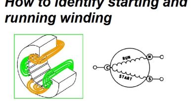
First of all, I want to clear you that we can control the fan motor speed using 3 methods in which we can do the ceiling fan motor speed control using two methods, while in stand fan motor we can also regulate the speed by doing the connections in axillary winding/starting winding. For ceiling fan speed control we use mostly two methods, in which one is by using speed control using a three or five-wire capacitor. And another one is using a dimmer switch from which we can control the RPM (revolutions per minute) of the ceiling fan or other fan motor.
So First we talk about ceiling fan speed wiring diagrams, I designed 4 diagrams in which I have shown the Off, low, med, and high-speed direction of the fan motor speed switch controller. Here is the fan speed low, high, and med speed direction diagram,
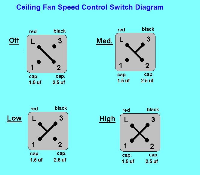
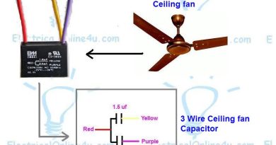
So As you know that by using 3 wire capacitor, we can control the speed of the motor using a speed regulator switch. So in the above diagram, I showed the switch in 4 types of diagrams. So for example our fan capacitor is 3 wire capacitor red, yellow and purple. So yellow for 1.5 µFand purple for 2.5 µF. So here is a complete diagram in which is shown the ceiling fan motor main winding and auxiliary winding/starting winding with speed controller switch, capacitor, and AC supply. In the below ceiling fan speed control switch diagram, I have shown the fan speed switch knob in the off direction.
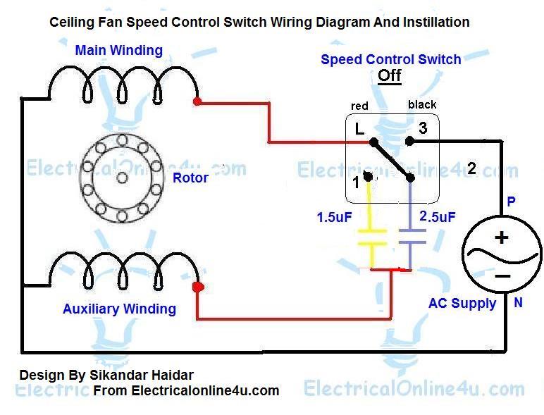
In the above ceiling fan speed control wiring diagram I have shown the main winding/running winding and I connect the run wire of the motor to the speed control switch, you can see in the above diagram that the connection of the “run wire” of the motor in switch L point and 1 and 2 for the capacitor. I connect the Purple color wire of the capacitor to the 2 number terminal of the speed Controller which is 2.5 microfarad and 1.5 µF to 1 point of speed which yellow wire of the capacitor. And red is the “common wire” of the capacitor and I connect this wire to the start point of the fan.
One thing more the phase (line) wire to 3 number point of the switch and neutral to common wire fan motor. So in the above diagram, the switch contacts on L to 2 which means that the 3-wire current is not connected to the fan and the fan is off.
So let’s see the low-speed wiring diagram of the fan.
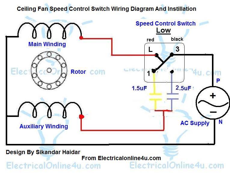
So in the above diagram, the fan speed regulating switch contacts on L, 3, and 1 side, and the line current starts to run wire of fan and 1.5 µF and the fan on low speed. let’s see the fan on med speed.
Also, Read
Ceiling fan capacitor connection diagram
3-wire ceiling fan capacitor diagram
5 wire ceiling fan capacitor diagram and installation
Role of Capacitor in fan and single phase motor
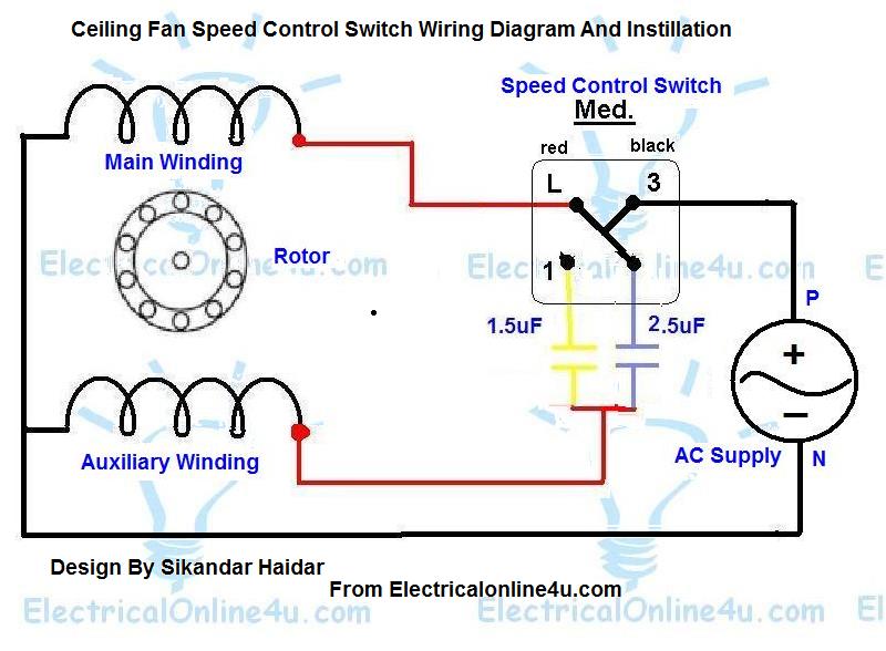
So in the above diagram the speed switch contacts on L, 3, and 2.5 µF, and the fan on running or start on 2.5 microfarad Cap and on med speed. Now let’s see the High speed of the fan diagram.
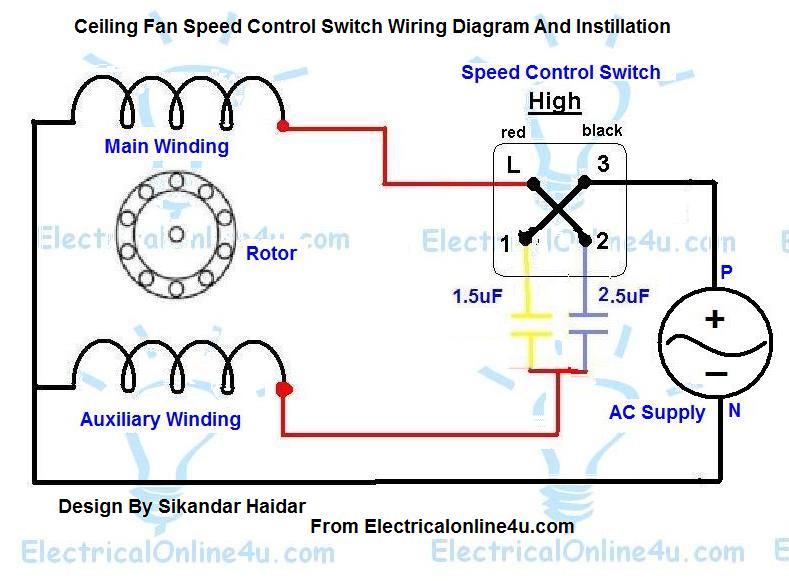
So in the high-speed direction of the speed controller switch, all contacts are connected with one another, and both 1.5 µF and 2.5 µF are connected to the motor, which means that 1.5 + 2.5 is 4 µF capacitor is connected to the fan motor. So a high capacitance number of capacitors is connected to the fan motor and the fan motor run fast on a high number of capacitors which 4 microfarad. One thing more is that doesn’t connect too a high-value capacitor which is out of the fan motor range. For example, if a motor required a 4 µF capacitor and you connect a 10 microfarad capacitor then the result will be bad, and the fan motor winding will be burned.
Fan controlling Speed Using Dimmer Switch
This is another method of controlling the speed of the ceiling fan, in which we use a dimmer switch from controlling or regulating speed. For a better understanding of the wiring connection of the dimmer switch read the below posts.
How to wire the dimmer switch for the ceiling fan?
Fan motor dimmer switch diagram
Message.
(Note that this a Basic guide of single phase AC (alternating current) fan speed regulating)
I hope now you understood the ceiling fan speed control wiring diagram or ceiling fan motor speed controlling switch diagram. Now if you have any questions regarding this post then you can use the comments section.

Hello and thanks so much for the information. I have a question and i would like you help me, Is possible to change the fan speed control by a leviton model RTF01 and how to be connected? regards
Thank you so much for having this information available. the speed switch on my fan had broken and having to change it has been a challenge. I don't quite understand why the line wire is on the #3 terminal, but that's how the original switch was wired. so I followed this information only to discover I had a defective switch. hopefully I'll get it fixed!
The fan connected without speed control switch fan have damage or any problm??