Ceiling Fan 3 Wire Capacitor Wiring Diagram
As you know we use single-phase types motors in ceiling fans and a ceiling fan required a capacitor to run. In-ceiling we use a capacitor, In which one type of capacitor has 3 wires. In this post, I am going to explain the ceiling fan 3 wire capacitor wiring diagram. This capacitor has 3 wires of which one is common for both and the other two for different value capacitance. This means that there are two capacitors instilled in this capacitor and both values are different from one another.
Ceiling Fan 3 Wire Capacitor Wiring Diagram
The 3 wire fan capacitor diagram is mostly available on capacitors but most people did not understood it. And he always tries to buy a 2-wire fan capacitor. But the 3-wire capacitor is better than 2 wire because we can use it for two different requirements.
In this capacitor one wire is common and between the common wire and 2nd wire, the capacitor is different than between the common and 3rd wire.
One thing more in some ceiling fans we use this type of capacitor for regulating speeds. I.e example” when the fan motor start at 1.5 µF the motor will be at low speed and when the capacitor is on 2.5 then the motor will be on med speed and when the ceiling fan motor run on both capacitor at the same time (1.5 + 2.5 = 4 µF) then the motor on high speed. And as I told you in my above words we can use it for a fan motor which only required the 1.5 microfarad capacitor.
However ceiling fan 3 wire capacitor we use in the fan mostly for speeds. In the fan, we use a speed regulator switch form which we can regulate the speed using a capacitor.
We have 3 wires in the ceiling fan capacitor in which red is common and the other two are for different capacitors values.
Also, read
How to connect a capacitor to the fan ( ceiling fan capacitor wiring diagram)?
What is the role of the capacitor in a fan?
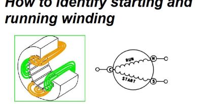
First, I am gonna explain the 3 wire capacitor diagram and you can easily learn from the below three wire capacitor diagram.

As shown in the above ceiling 3 wire capacitor diagram red is common wire and yellow for 1.5 microfarad and Purple for 2.5 microfarad. However, IN SHA ALLAH in the further post, I will explain the fan 5 wire capacitor, regulating speed switch diagram, and replacement of the fan capacitor in the fan motor.
Now I hope you understood the ceiling fan 3 wire capacitor wiring diagram. Now if you have any questions or suggestions then post in the comments box below.

I have 3 wire capacitor that is 1mf and as a gray wire on one end and a yellow and blue on the other end. I have a white wire coming from the direction switch and they need to be wired to the 3 speed switch. I believe the black wire coming from the power goes to L but need to know how the other three wires are wired to the switch 1.2.3
Lighting decor is the perfect home accent when you are decorating or redecorating your home. And as you, the NHL Hockey fan, there is no better way to show off your team spirit and loyalty than by proudly displaying sports-themed hockey lamps and lighting products throughout your house using these products which are functional, practical and trendsetting. With so many to choose fun, your entire family can get involved and decorate their room with their favorite team. Ceiling Lights
click to read more
Because of this protecting layer, DC flow can not course through the capacitor as it blocks it permitting rather a voltage to be available across the plates as an electrical charge. high voltage resistor manufacturer
These conductive plates can be either round, rectangular or tube shaped fit as a fiddle with the dielectric protecting layer being air, waxed paper, plastic or some type of a fluid gel as utilized in electrolytic capacitors. high voltage diode manufacturer
Basically, any individual who needs to turn into a designer, ought to follow his space of interest. These two parts of engineering make up our reality, subsequently, there is a ton to look over. power mosfet manufacturer
I conceive this website has very wonderful indited content material posts . Unique Dofollow Backlinks
How capacitor is connected to ceiling fan diagram?
URL: https://affordablelectricians.com.au/electrician-hawthorn.html
https://www.affordablelectricians.com.au/electrician-hawthorn.html
But again most air conditioners have three terminals on the capacitor. Now the capacitor also also labeled with fan C. In turn for each of the three terminals. We're going to take our Brown wire.
Watch and Download world's famous drama series Kurulus Osman in English on link below
👇
Kurulus Osman in English
📢Get free .com domain name and start your own website
Free .com domain name
Crypto trading online course
Join on link below
Crypto quantum leap
📒 Read Home doctor book online
Then you will be a doctor for your family
Home Doctor Book
💰Create own NFTs and earn 1000$
Complete guide
Create NFT
Join online YouTube course
And be a professional YouTuber
Tube Mastery and Monetization by matt
🦷Steel Bite Pro
Best product for
Teeth pain, cavities,teeth whitening and other oral health issues with money back guarantee
Steel Bite Pro