How To Wire Ammeter For DC and AC Diagram
In my last post, I wrote about the ammeter and now this post is about ammeter wiring, In this post, I will completer guide you about the ammeter wiring and its wiring diagram which I design for those students who can not learn from difficult diagrams.
In this article, we clear some most important questions which make a problem for the electrical student. I always try to teach students in an advance and easy way.
Also, Read below
what are an ammeter or ampere meter and what role of a meter
How to Wire an Ammeter or Ampere meter
We know that the flow of electrons in an electric circuit is called current and current is denoted by I and its unit is Ampere Which we denoted by “A”.
Note ammeter wiring is always in series connection but this is only for low load, For high load measurement or testing ampere we use the CT coil with an ampere meter to measure the A.
In this article, we talk about low load, and for the low load, we wire an ammeter in series with a circuit.
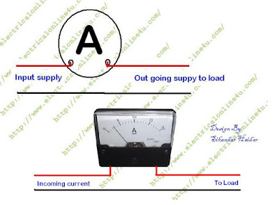
In the below diagram, I have shown how to wire an amp meter, in the diagram I have shown two wire coolers of which one is Black and the second is Red. You called these black and red cooler wires positive and negative for DC (Direct Current) or you can also call these coolers neutral and Phase for AC (Alternative Current).
The DC and AC ammeter wiring method is the same but for DC you will use a DC ammeter and for AC measurement we can only use the AC ampere meter.
I hope now you will completely understand the ammeter wiring, In my incoming post, I will share with you a diagram that how to wire an ammeter for high loads with a CT coil which also helps you in power wiring or 3 Phase wiring.